The 2D and 3D transducer models are created in Ansys DesignModeler and meshed in the Ansys Mechanical Application. The major axis length is 450 mm and the minor axis length is 210 mm.
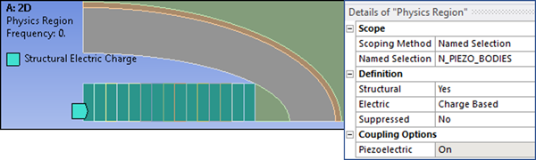
In both the 2D and 3D models, the first Physics Region object is scoped to all piezoelectric bodies. Structural is set to Yes and Electric is set to Charge Based.
In the 2D model, the second Physics Region object is structural and is scoped to all other bodies. The fluid region is included because Mechanical does not support defining acoustic behavior for 2D fluid bodies. The fluid region is defined later using a command snippet (see 2D Transducer Model).
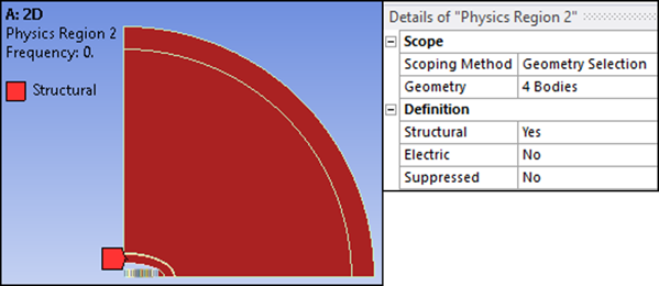
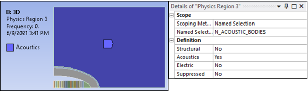
In the 3D model, the second Physics Region is structural and is scoped to the aluminum shell and the rubber boot. The third Physics Region is acoustic, as shown in the figure below.
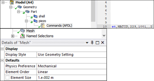
For the 2D case, the ceramic stacks are modeled with PLANE223 coupled field (piezoelectric) elements with dropped midside nodes. PLANE182 structural elements are used for the aluminum shell and rubber boot.
Workbench does not support the PLANE223 element with dropped midside nodes. The workaround is to define element type PLANE223 using a command snippet, and set Element Order to Linear for the Mesh object as shown below:
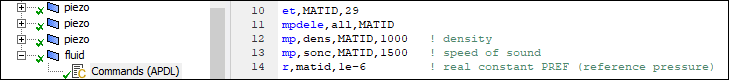
The surrounding water is a circular region meshed with FLUID29 acoustic elements with a radius of 1.1 m. Workbench does not support the FLUID29 element, but you can define it using a command snippet as shown below:
The truncated boundary defined by the 1.1 m circular arc is meshed with FLUID129 infinite acoustic elements to absorb outgoing acoustic waves. The FLUID129 elements are also created by a command snippet (see Figure 33.12: Acoustic Boundary Conditions for 2D Model).
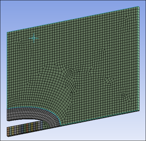
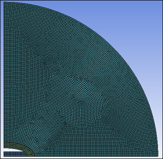
The following figure shows the final mesh with an average element size of 10 mm:
For the 3D case, the ceramic stacks are modeled with SOLID226 coupled field (piezoelectric) elements with dropped midside nodes. SOLID185 structural elements are used for the aluminum shell and rubber boot.
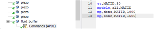
A rectangular region 300 mm from the sides of the transducer represents the surrounding water, which is modeled with FLUID30 acoustic elements. The model is extruded 10 mm in the out-of-plane (z axis) direction to create a 2.5-D representation.
Workbench does not support the FLUID30 element, but you can define it using a command snippet as shown below:
The following figure shows the final mesh with an average element size of 10 mm: