The result object Scoping Method option, Result File Item, enables you to scope a result to the following Mechanical APDL Solver generated data items generated in the result (.rst) file, once you have performed a solution:
: The material ID assigned to the element by Mechanical APDL.
: Mechanical APDL element name string such as BEAM188, SOLID185, and SURF154. In addition, for this option, you can enter an element group label, such as "beam", to include all beam element types. Supported group labels include:
COMBIN
MASS
LINK
PLANE
SOLID
SHELL
SURF
TARGE
CONTAC
BEAM
PIPE
ELBOW
FOLLW
FLUID
PRETS
MPC
INTER
SOLSH
See the Element Library section of the Mechanical APDL Element Reference for a complete listing of all available elements.
: The element type ID assigned to the element by Mechanical APDL.
: Component names are created by the Mechanical APDL Solver. Components are node- or element-based groupings, node- and element-based Name Selections that were written to the result file from Mechanical, or components that the solver needed to generate in order to properly solve the analysis. Solver generated components typically contain an underscore (i.e. "_") at the beginning of the Component Name.
and : During the mesh process, the application assigns each element and node of the model an ID. The application sends the ID values to the solver during the solution process. Once complete, you can scope one or more element or node IDs to a result. In addition, the solver may generate new elements, not included in the original mesh, in order to process loads, contact conditions, or support conditions. The application also assigns an ID to these elements as well as the elements corresponding nodes. You can also use these system generated element and node IDs for further post processing.
This scoping option is unique in that it obtains data from the result file following the solution. This section examines the following topics for this feature. Select a link to jump to that topic.
Background
During the solution process, Mechanical identifies nodes and elements contained in the mesh and sends this data to the solver for analysis processing. An element is identified by an element type number, an element name and a material number. A typical element name, such as SOLID285, consisting of a group label (SOLID) and a unique, identifying number (285).
Additional elements, nodes, and groups of nodes or elements, not included in the original mesh, may also be created to process loads, contact conditions, or support conditions, that are required to properly solve the analysis. Once the solution is complete, the data is written to the result file, and the element data, as well as material data, becomes available to you.
In addition, during the solution process, node and element Name Selections are also written to the result file and may be selected for scoping. The Mechanical solve process may also create additional components for use in solving the analysis. The components typically contain an underscore (i.e. "_") at the beginning of the Component Name.
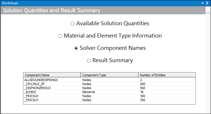
The application presents this information in the Solution Summary Worksheet, using the Material and Element Type Information and Solver Component Names options. As illustrated below, the Worksheet option Material and Element Type Information lists Material IDs, Element Name IDs, and Element Type IDs generated during the solution as well as other appropriate information such as Element Shape. The Solver Component Names option lists the solver generated Component Name as well as the Component Type (nodes or elements) and the Number of Entities. The Component Name always includes an underscore prefix.
| Material and Element Type Information |
|
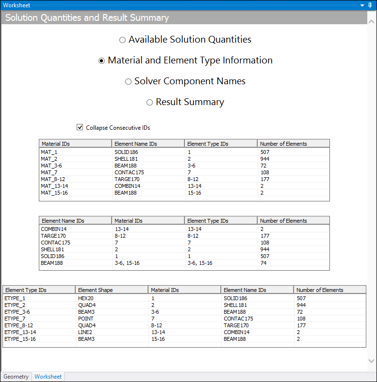
Note: The Material and Element Type Information option does not display elements for a Material ID value of 0. Important: If your analysis includes a Condensed Part and a result is using the option for the Scoping Method, Material IDs and Element Name IDs are not available for the Material and Element Type Information selection on the Solution Quantities and Result Summary page. |
| Solver Component Names |
|
|
Application
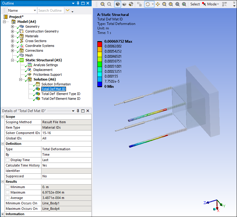
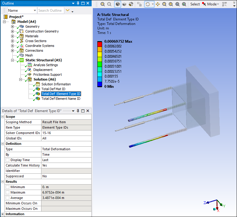
Once you solve your analysis, you can select the Result File Item option for the Scoping Method of the desired result object in the Details view, as illustrated below for a total Deformation result.
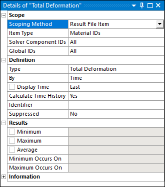
When you specify the Scoping Method as Result File Item, the following additional properties display in the Details view:
Item Type: The options for this property include (default), , , and .
Solver Component IDs: Based on the option selected in the Item Type property, you enter the appropriate ID or in this property as listed in the Worksheet. The default value is . You can enter a number or a number range (that is, 1, 2, 3, or 2-5). For , you enter a element name, such as BEAM188, or you can simply enter "beam" to include all beam element types.
Global IDs: This property is used to scope results to bodies that have the Model Type property set to . This property is not applicable to bodies with any other Model Type setting. The application assigns a global ID to each body contained under the Geometry object, in the order that they are listed. That is, the first body in the tree has a global ID of 1 and so on in descending order for each object. As a result, you must determine the Global ID of your reinforcement bodies based on their position in the tree. The default setting for the Global IDs property is . You can enter an individual ID, or a range of IDs based on the number of reinforcement bodies. See the Reinforcement Specification Using Mesh-Independent Method for additional information about performing reinforcement analyses.
Note:
The assignment of a Global ID is not affected (changed) if you Group body objects.
You may encounter a rare case when you are scoping a result to a solver component for a body that contains multiple materials. In this instance, set the Mesh Source property (Solution object) to the option .
Examples
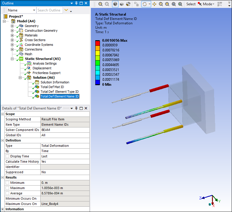
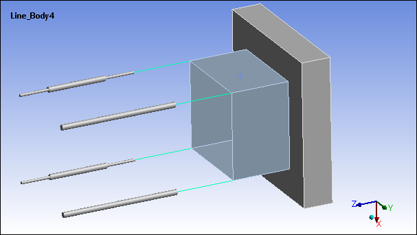
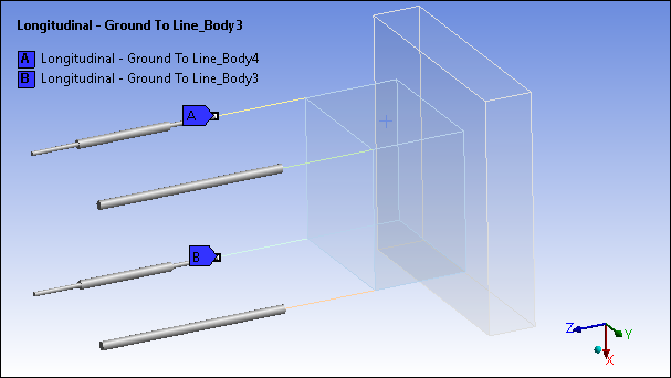
Here is an example model. It includes four line bodies as well as two user-created beam connections.
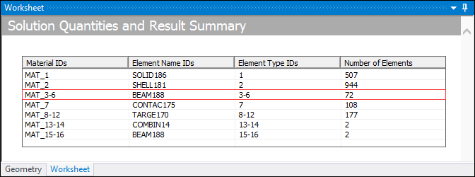
Examining the Worksheet following a solution process for the material and element data, we have the following. We are going to further examine the beam connections that correspond with Materials 15 and 16 (Element Type ID as well).
The following sequence of Total Deformation results illustrate the Result File Type scoping options, Material ID, Element Type ID, and Element Name ID. Note that the Material ID and Element Type ID present the same result data using different scoping options.
For this example, we generalized the Element Name and used "Beam." This generates results for the additional (four) line bodies of the model as well as the beam connections.