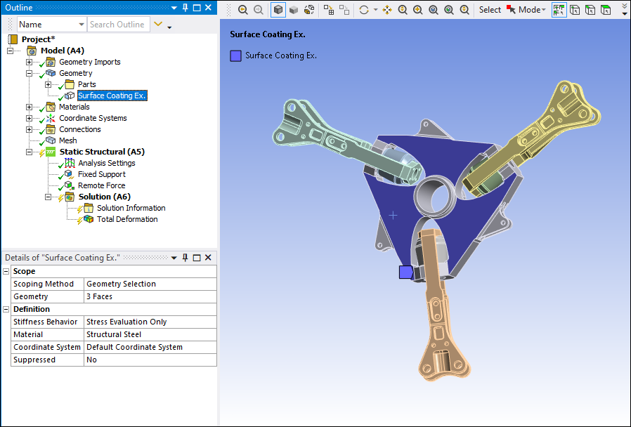
You can apply a Surface Coating to your model using the option from the Modify group on the Geometry Context Tab. You can apply one or more of these coatings, or layers, to the faces of your model. This feature places shell elements of a specified material and thickness on the selected face or faces of your model.
Once properly defined, you can use these surface coating definitions as a Scoping Method for results. The Surface Coating scoping option is supported by most result types, including User Defined results. During the solution process, the Mechanical APDL solver specifies the elements as either SHELL181 (low order) or SHELL281 (high order).
Important: To retrieve normal stress component Sz, where z is the shell’s normal direction, you must make sure of the following:
KEYOPT(10) = 1 and,
Pressure loads are applied directly to the shell structure.
If these settings are not specified, the application reports the Sz results as zero in the element coordinate system. Furthermore, applying loads such as displacements, forces, or pressures using the Surface Effect option of the Applied By property, also does not retrieve Sz results. See the SHELL181 and SHELL281 Element Reference sections for more information.
Important: During a Cyclic Symmetry analysis, the application does not expand Surface Coating results.
A Surface Coating is defined in the following example.
Surface Coating is an available option for the Scoping Method property.
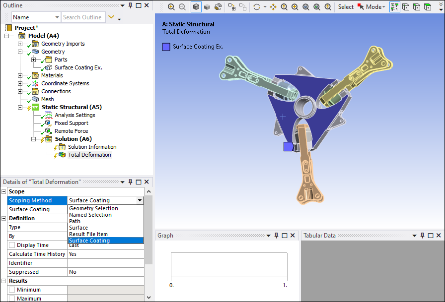
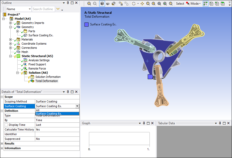
When the Scoping Method is set to , an associated Surface Coating property displays and is used to select the coating defined under the Geometry object (). If multiple coatings were specified, they would display in the drop-down list of this Surface Coating property. The default option for this property is .
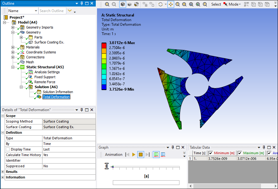
Here is the evaluated result.