


Go to a section topic:
Supported Scoping Types
All result objects can be scoped to:
Geometry selections - edges, a single vertex, faces, parts, bodies, or the entire assembly ().
Geometry-based Named Selections.
Node selections of the underlying mesh.
Element or Element Face selections of the underlying mesh.
Result Object Scoping Requirements
Make sure that your result objects conform to the following:
If you scope a result to one or more geometric entities (body, face, edge, or vertex) and subsequently suppress all of the bodies associated with the scoped entities, the application, by default, sets the scoping to . However, the application still stores the suppressed geometric entity set for future reference. Therefore, if any of the bodies associated with the scoped entities are later unsuppressed, the result scoping is set back to the originally defined (unsuppressed) geometric entities. If this behavior is undesirable, it is recommended that you use a Named Selection to define the scoping of the result.
Once a solution is computed, the scope of the result object cannot change. You must either add a new result object with the desired scope, or you can right-click that result item, and choose to change its scope.
Result scoping has an effect on convergence. Refinement does not happen outside the scope for a given convergence control. Multiple convergence controls are possible, however.
Node-Based Scoping
The following are known characteristics related to node-based scoping:
If all nodes of an element face are scoped, then Mechanical will draw contour bands on the entire face.
If some nodes of an element face are not scoped, then Mechanical will draw the face as transparent and draw the scoped nodes in contour colors.
As is the case with other scoping that occurs within a body (such as vertex or edge), any applicable averaging is done considering all of the nodes on a body.
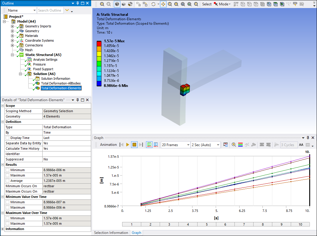
Element-Based Scoping Result Evaluation
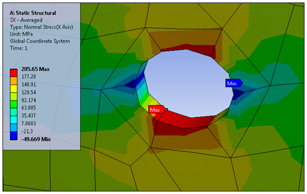
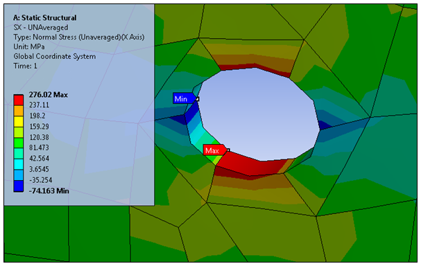
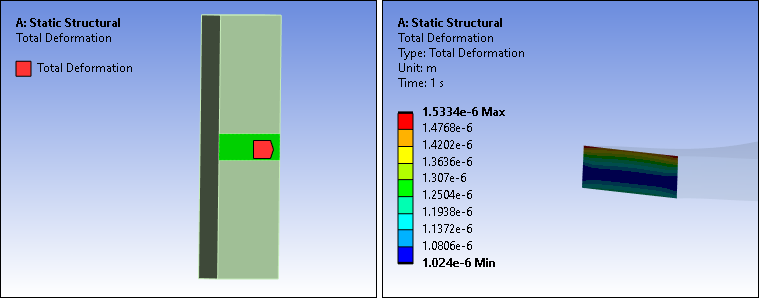
Unlike results scoped to geometries or nodes, results scoped to elements evaluate only the scoped elements. No adjacent elements are considered. The example results shown below illustrate this behavior. Refer to the Averaged vs. Unaveraged Contour Results section of the Help for additional information on this topic. The following results illustrate contour bands for all nodes.
|
Global Averaged Result Max. = 205 and Min. = -50 |
Global Unaveraged Result Max. = 276 and Min. = -74 |
|
|
|
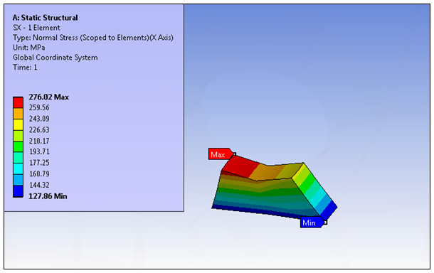
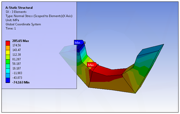
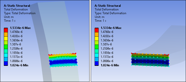
The following results illustrate contour bands for elements only.
|
Result Scoped to One Element Max. = 276: Matches the Global Unaveraged Result (Min. Value = 127) |
Result Scoped to Three Elements Max. = 205: Matches the Global Averaged Result Min. = -74: Matches the Global Unaveraged Result |
|
|
|
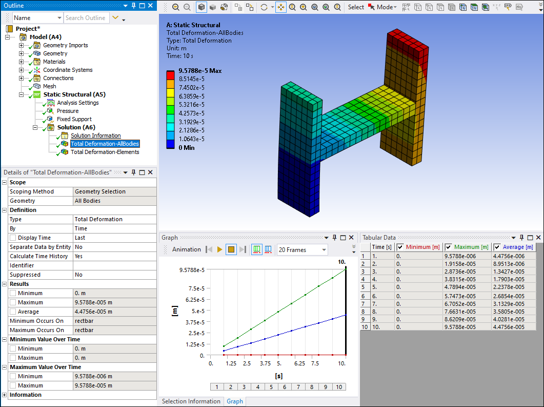
Separating Result Data by Entity
In the Definition category of the Details pane, result objects include the property: Separate Data by Entity. Options include and (default). This property enables you to display individual minimum and maximum values for each scoped entity of the result, such as 2 bodies, 3 Faces, 5 elements, etc. Be sure to review the limitations listed below before using this property.
When set to , result data displays normally, and the Tabular Data window displays one column for the global Minimum and one column for the global Maximum value for each time step.
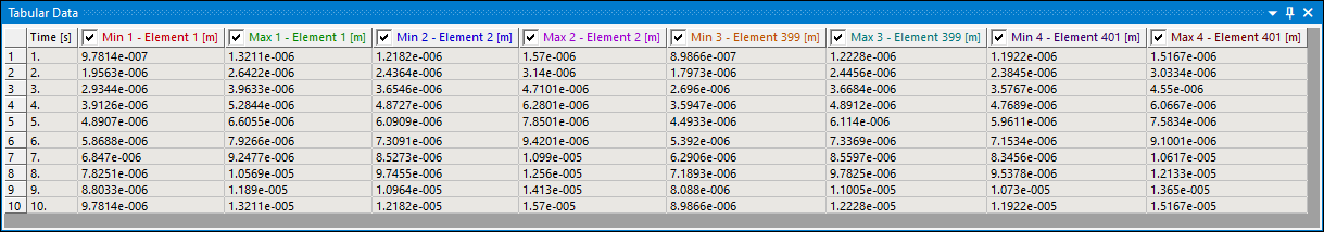
When you set this property to , the application calculates and displays local Minimum and Maximum values for each scoped entities and displays each separately in the Tabular Data window. For the scoped entities, each column header in the window displays either a Node ID, Element ID, or the title "Reference" for geometric entities. Note that the global minimum and maximum values are not displayed when the property is set to Yes.
Note that the Separating Result Data by Entity property does not support:
Vector Principal Stress and Vector Principal Strain results.
Fatigue Results (Fatigue Tool), Contact Results (Contact Tool).
Solution Combination results.
Results scoped to a Construction Geometry or .
Results with the Display Option property set to .
Coordinate System Results: Nodal Triads, Nodal Euler XY/YZ/XZ Angle, Elemental Triads, Elemental Euler XY/YZ/XZ Angle.
Geometry Selection Limitation for Node-Based Results
Illustrated below are two bodies that share a singular face but that are not in contact.
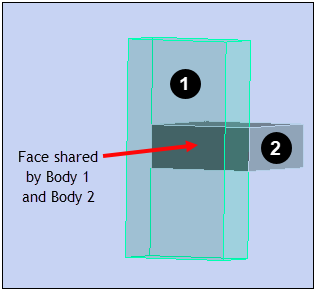
When you scope a node-based result type, such as deformation, to either of the faces, contour results are displayed on only one of the faces. As shown, this face may not be the one you selected.
To display contour results on both bodies with a shared face for a node-based result type (only), create a Named Selection for the shared face, and scope to the Named Selection.
Tip: To display contour results on both bodies of a shared face for any result type, clear the result, create a Named Selection on one of the faces, and solve the simulation. Open the Worksheet from the Solution object and select Solver Component Names. On this page of the Worksheet, you will see a node-based component for the Named Selection. You can now scope your node-based result to this component to produce the desired results for both faces of the associated bodies.