From the Project Schematic, Workbench and Mechanical enable you to link and transfer the deformed geometry and mesh that are based on a Deformation result, from a Static Structural, Transient Structural, Modal, Eigenvalue Buckling, Explicit Dynamics, or LS-DYNA system to a Mechanical Model system or to (any) Mechanical analysis system.
Important:
Your analysis must use the Mechanical APDL solver or the AUTODYN solver.
The AUTODYN solver does not support the Particle (SPH) Reference Frame for this feature.
This approach is ideal for using a displaced structure as the initial geometry of a subsequent analysis. For example, you might wish to introduce imperfections to an otherwise perfect geometry to overcome convergence issues when running a nonlinear simulation.
Specifications and Limitations
Note the following:
Named Selections (face-, node-, and elemental-based) transfer from the upstream system.
The application creates the deformed geometry using the unit system of the result file, that is, the unit system that was used during the solution of the upstream system.
Property specifications made to the bodies of the geometry in the upstream systems transfer to the downstream system. These specifications are, by default, read-only in the downstream analysis system. A Details view category, Transfer Properties, provides the Source name of the upstream system and provides an option to change the object's properties from . If the Read Only property for a body is changed to , the property specifications made in the upstream system will not transfer when data is refreshed.
Property specifications made on the Geometry object of the upstream system do not transfer to the downstream system.
Rigid and Gasket bodies do not transfer.
Materials transfer only when the upstream and downstream systems share the Engineering Data cell.
The application does not support the transfer of 1) Material Assignment objects or 2) bodies whose material is defined by a Material Assignment object.
This option does not support a Nonlinear Adaptive Region.
Important: For line bodies, the nodal coordinates of the orientation nodes are not updated and remain the same as the initial geometry/mesh. Therefore, carefully validate the results of any analysis that uses the deformed geometry if the initial geometry has line bodies.
Application
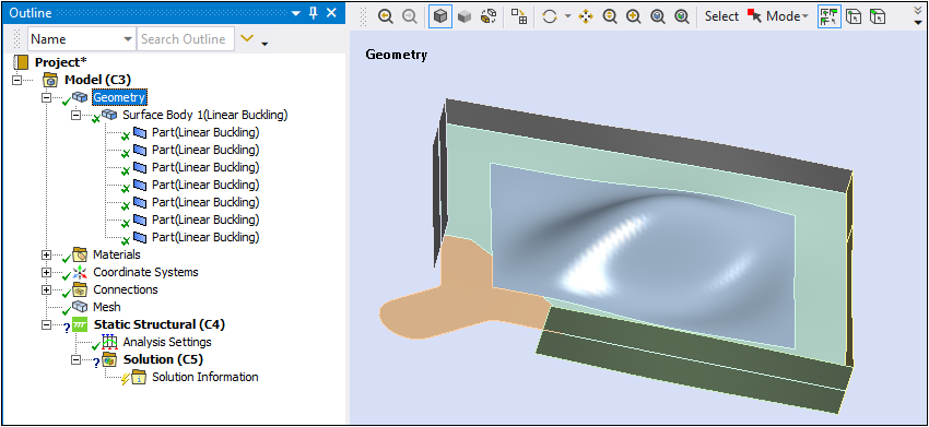
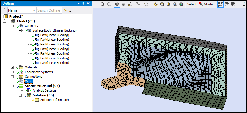
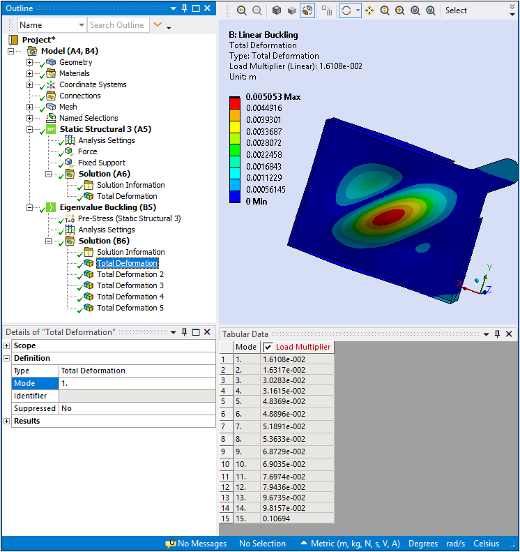
Identify the deformation result within the solved analysis that you wish to use. An example Eigenvalue Buckling analysis is illustrated below. The result to be specified is the first result (Mode =
1).
Return to the Project Schematic and link the Mechanical Solution cell to the Model cell of the downstream Mechanical system. You can create links from the Solution cell to multiple downstream Model cells.
In the continued example shown here, the Solution cell is selected. Note the properties under the heading "Update Settings for Static Structural 2", the new downstream system. If multiple links are present, there is an instance of the "Update Settings for Analysis Type" in the properties for each linked analysis. If you change a setting in properties for a linked system, this causes the data for all of the other downstream systems to become obsolete and you need to refresh the data on each system.
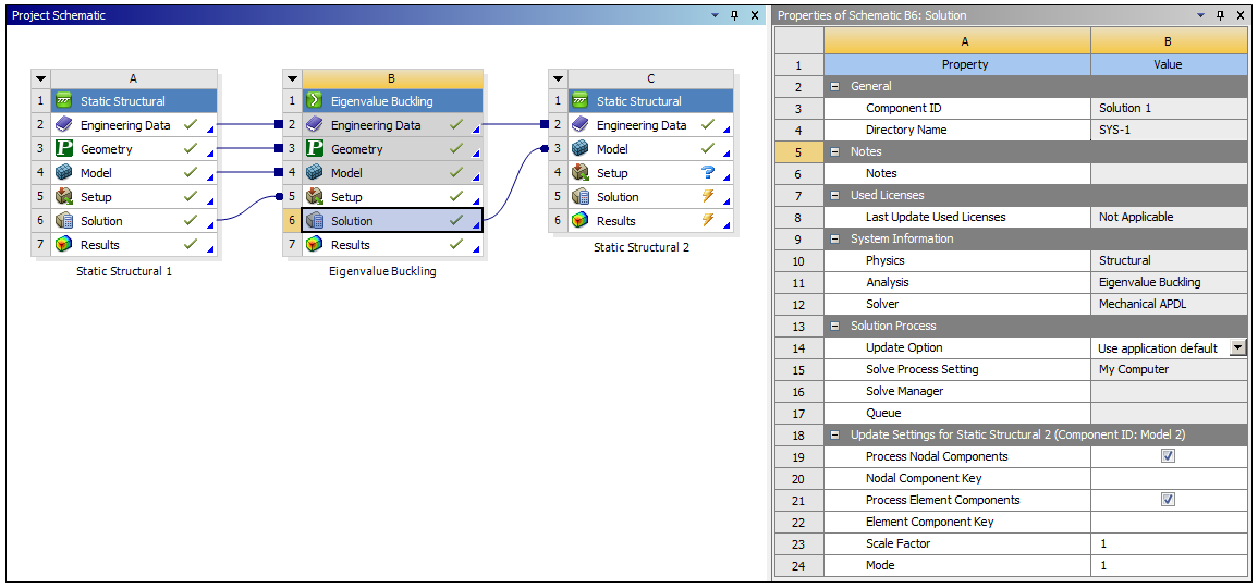
The properties include:
Process Nodal Components: Enables the upstream system to import node-based components defined in the mesh files. The application transfers the data to downstream Mechanical systems as node-based Named Selections. The application renames the node-based Named Selection objects in Mechanical based on the selection made in the Object Renaming property.
Nodal Component Key: This entry field enables you to filter and import only those node-based components that start with a specified name/string value in the mesh files. For example, you want to import only node-based components that start with the prefix string "
nodal_*." Enter that string into this field and the application filters through all component names and returns only the components that begin with this key string value.Process Element Components: Enables the upstream system to import any element-based components defined in the mesh files. The application transfers data to downstream Mechanical systems as elemental-based Named Selections. The application renames the element-based Named Selection objects in Mechanical based on the selection made in the Object Renaming property.
Element Component Key: This entry field enables you to filter and import only those element-based components that start with a specified name/string value in the mesh files. For example, you want to import only element-based components that start with the prefix string "
elemental_*." Enter that string into this field and the application filters through all component names and returns only the components that begin with this string value.Scale Factor: this property scales the displacements of the initial configuration. If Scale Factor is
1.0, the full displacement value will be added to each node,0.5, half the displacement value will be added, and so on. Negative Scale Factor values subtract the displacements and reverse the direction of deformation.Time/Mode: this property is based on the analysis system.
For a Static Structural, Transient Structural, or Explicit Dynamics system, you specify a Time setting for the upstream system's results for each downstream Model cell. The Time property options include (default) and .
For Eigenvalue Buckling or Modal systems, you specify the desired Mode, for each connection to a downstream Model cell. In this bucking example, it is Mode, and displays the result that you selected in the buckling analysis (Mode = 1) to use as your geometry and mesh in this subsequent analysis. You can change the desired/target result at this time (to Mode = 2, 3, etc.).
Important:If you enter a Time value that is greater than the end time of the upstream analysis, the result generated for the deformed geometry assumes the final time. If specified by Mode, and you enter a Mode value greater than the maximum number reported by the solution, geometry generation fails.
If you enter a User Defined time of
0, the application generates the geometry at the End Time.
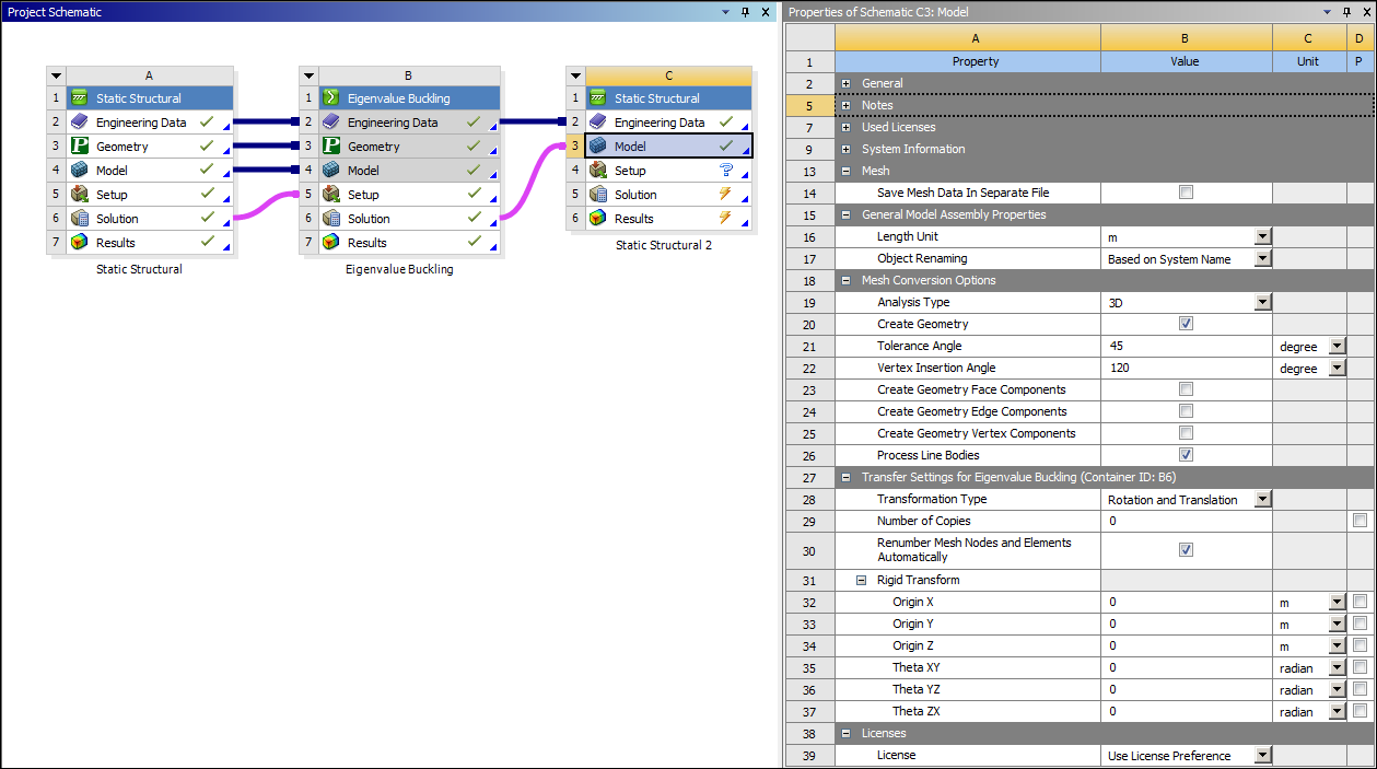
The Model cell is selected in the example shown below for the new system. Specify any Model Assembly or Mesh Conversion Options on the Model cell of the downstream system to modify or assemble the new geometry.
Note: If you are incorporating a deformed geometry into Model Assembly systems, you need to share the Engineering Data cell of the deformed geometry system with one or more of the Model Assembly systems in order to have the materials automatically transferred and set for the deformed geometry in the downstream system.
Open the new system in Mechanical. The new geometry and the mesh are transferred.
Note: When you are using a deformation result as a geometry, the same behavioral characteristics as well as limitations apply as those associated with importing mesh-based geometries. See the Requirements and Limitations topic of in the Import Workflow and Interface Options section of the Help for specific information.