


From the Project Schematic, Workbench and Mechanical enable you to link and transfer updated geometry and connections that are based on a simulation result from a Rigid Dynamics system to a Mechanical Model system or to any Mechanical analysis system.
This approach is ideal for using a displaced model as the initial geometry of a subsequent analysis. For example, you may wish to convert one body from rigid to flexible and perform a static analysis at a given configuration using the corresponding motion loads. It is also useful when the analysis of one single component is not accurate enough. This can be the case if contact exists on the parts of interest for the stress analysis.
Specification and Limitations
Note the following:
The application creates the updated geometry using the unit system of the result file (the unit system that was used during the solution of the upstream system).
Property specifications made to the bodies of the geometry in the upstream system transfers to the downstream system. These specifications are, by default, read-only in the downstream system. A Details view category, Transfer Properties, provides the Source name of the upstream system and provides an option to change the object's properties from Read Only. If the Read Only property for a body is changed to No, the property specifications made in the upstream system will not transfer when the data is refreshed.
Property specifications made on the Geometry object of the upstream system do not transfer to the downstream system.
Joints Initial Position property in the downstream system will be set to Override.
Flexible, Line, and Gasket Bodies are not supported.
Nonlinear spring and bushing properties are identical to those in the upstream properties, and are not re-evaluated around the new operating point.
Application
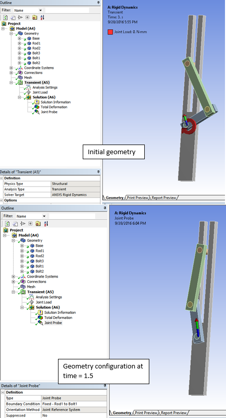
Identify the configuration results within the solved analysis that you wish to use. An example is shown below. The configuration to be specified is the result at time = 1.5.
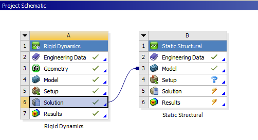
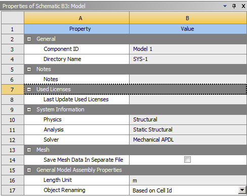
Return to the Project Schematic and link the Mechanical Solution cell to the Model cell of the downstream Mechanical system.
If you change a setting in certain properties for the linked system, the data of the downstream system becomes obsolete and you should refresh the data on the system.
Properties which cause the downstream system to become obsolete include:
Time: For a Rigid Dynamics system, specify a Time setting for the upstream system's results for the downstream Model cell. The Time property can be set to End Time or User Defined.
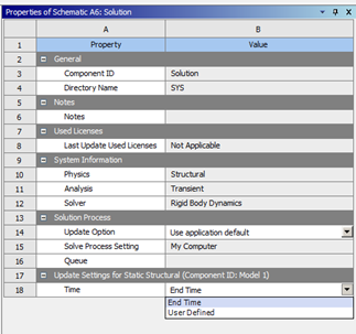
Important: If you enter a Time value that is greater than the end time of the upstream analysis, the result generated for the updated geometry uses the end time. If you enter a User Defined time of 0, the application also uses the geometry from the end time of the analysis. This differs from the imported geometry in that the model is assembled at time = 0 to satisfy all kinematic constraints (joints, joint conditions, and user-defined constraint equations).
Open the new system in Mechanical. The new geometry and the updated connections are transferred.