


The Mechanical Model system launches the Mechanical application, allowing you to create an analysis using a single model and multiple system analysis branches. You can also create other Mechanical Model systems that share data at any cell level (Engineering Data, Geometry, or Model). Mechanical Model Model systems are unfiltered (physics and solver).
The system consists of Engineering Data, Geometry, and Model cells. In the Mechanical application, this system corresponds to that of a Model-only system.
This system is created when you resume a legacy database that does not have an analysis environment already defined. It can also be used as a system replacement for a Mesh system.
Working Through a Mechanical Model system
To work through a Mechanical Model system:
To add a Mechanical Model component system, drag the system from the Toolbox to the Project Schematic or double-click the system in the Toolbox.
Create or attach a geometry using the Geometry cell context menu.
If required, right-click the Model cell and select to edit the model.
To add a connected system, either drag a valid analysis system from the Toolbox and drop it on the appropriate target location, or right-click the Geometry or Model cell and select from the context menu.
To create multiple system analysis branches, repeat step 4 with other analysis systems.
Resuming an Existing Legacy Database
To resume an existing legacy database that contains no physics environment:
From the menu bar, select > .
Browse to the legacy database, select it, and click .
A Mechanical Model system appears in the Project Schematic, with the legacy database loaded.
To open the Mechanical application, double-click the Model cell, or right-click the cell and select from the cell context menu.
In the Mechanical application, complete any necessary model updates.
To add a connected system, either drag a valid analysis system from the Toolbox and drop it on the appropriate target location, or right-click the Geometry or Model cell and select from the context menu.
Continue with the analysis in the analysis system as you normally would.
Replacing a Mesh System with a Mechanical Model System
To replace an existing Mesh system with a Mechanical Model system (or vice-versa), right-click the system header and select > or > (respectively) from the context menu. When a Mesh system is replaced with a Mechanical Model system, the Mechanical Model system can then be shared with any analysis system as described above.
The units setting specified in an existing system is not maintained in the replacement system. In the replacement system, you must select the units setting that you want to use.
Multiple Mechanical Model component systems can be merged together by creating a connection between the Model cells of each component system. This allows you to build up more complicated models from smaller, simpler models. This behaves in the same way as Mesh-to-Mesh Connections. More detailed information can be found in Assembling External Models and Mechanical Models in the Mechanical User's Guide.
You can transfer a deformed geometry from a Static/Transient/Modal/Buckling/Explicit Dynamics system to a Mechanicall Model or to a Mechanical analysis system. You might want to do this to introduce imperfections to an otherwise perfect geometry to overcome convergence issues when running a nonlinear simulation.
To use the deformed mesh from a solved analysis as the initial geometry/mesh for a follow-on analysis:
Drag a connection from the Mechanical Solution cell to a downstream Model cell in a Mechanical system.
You can create connections to multiple downstream Model cells.
To share Engineering Data between the systems, link the Engineering Data cells as required.
Note: If you are incorporating a deformed geometry into Model Assembly systems, you need to share the Engineering Data cell of the deformed geometry system with one or more of the Model Assembly systems in order to have the materials automatically transferred and set for the deformed geometry in the downstream system.
Optionally, in the Properties pane:
Adjust the amount and direction of the deformation by setting a Scale Factor (a negative value reverses the direction of the deformation).
Adjust the upstream Time settings (for Transient, Static Structural, or Explicit Dynamics systems) or the Mode (for Eigenvalue Buckling or Modal systems) for each connection to a downstream Model cell.
If you set a User Defined Time, the value is always interpreted as being in seconds.
Adjust the transfer input settings on downstream Model. The transfer settings are the same as those for Mesh-to-Mesh Connections.
For more detailed information, see Geometry from Deformation Results in the Mechanical User's Guide.
When you connect the Model cell of a Mechanical system to the Model cell of a
downstream Mechanical system, you can use the Renumber Mesh Nodes and
Elements Automatically property in the downstream Mechanical Model cell
to control whether mesh nodes and elements are automatically renumbered to prevent
conflicts. You can set the Renumber Mesh Nodes and Elements
Automatically property on a transfer-by-transfer basis. By default
automatic renumbering occurs, but you can disable the property for as many of the
transfers as you want—as long as their element numbers will not conflict
downstream and the Number Of Copies is set to
0.
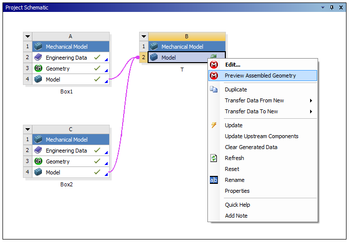
You can quickly preview the orientation of your parts in an assembly by right-clicking on the downstream model cell and selecting Preview Assembled Geometry. When using this feature, Mechanical assembles the geometry only (computationally expensive items such as the mesh are not assembled), allowing you to review the assembled geometry quickly. This feature is useful if you are unsure about the relative positioning of your subassemblies and some transformations are required for proper alignment.
Example Workflow
To start, you must have fully updated upstream Model cells
connected to a downstream Model cell. The downstream
Model cell is in a state of refresh required. In this
demonstration, Box1 and Box2 are both the
same model, a rectangular prism, and you would like to have them oriented into a
“T” (one oriented 90 degrees from the other). However, a translation
in the positive y-direction is also needed to ensure a smooth contact between the
parts. To accomplish this, enter a value of 10 m in the
Properties pane of the Project
Schematic to translate the Y-origin of Box1. As
opposed to issuing a full update on the downstream Model cell,
which loads the mesh data as well as the geometry, you first perform a geometry-only
assembly by right-clicking on the downstream model cell and selecting
Preview Assembled Geometry.
This opens the assembly in Mechanical for you to inspect. When you activate Mechanical in this way, no meshing or physics options are available.
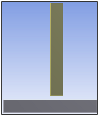
Upon viewing the preview, you discover that the geometry is not in the proper orientation. After inspecting the gap between the parts, you determine the proper y-translation is 9.35 m. After entering this data in the Properties pane of the Project Schematic, you can again right-click the downstream Model cell and select Preview Assembled Geometry. Mechanical will quickly update to show you the change in orientation.
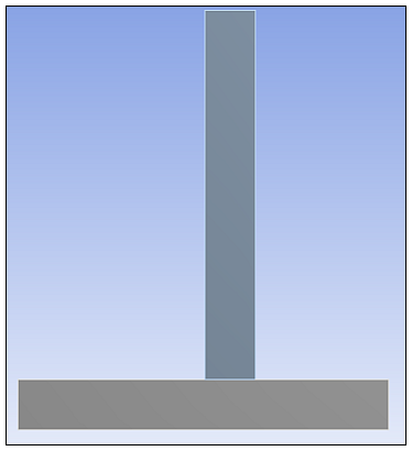
You confirm that the orientation of the two parts is correct. At this point, you can issue a full update so that Mechanical loads in the mesh data and you can continue your analysis.