


The steps for defining a semi-elliptical crack are presented here.
Select the Model object in the Tree Outline.
Insert a Fracture object into the tree by right-clicking on the Model object and selecting Insert > Fracture from the context menu. Alternatively, select the Fracture option from the Define group on the Model Context Tab.
Note: Only one Fracture object is valid per Model.
Insert a Semi-Elliptical Crack object into the Tree by right-clicking on the Fracture object and selecting Insert > Semi-Elliptical Crack from the context menu. Alternatively, click the Semi-Elliptical Crack from the Crack group of the Fracture Context Tab.
A semi-elliptical crack definition must always be scoped to a single solid body. Use the Body selection filter to pick a body in the Geometry window, click the Geometry field in the Details View, and then click Apply.
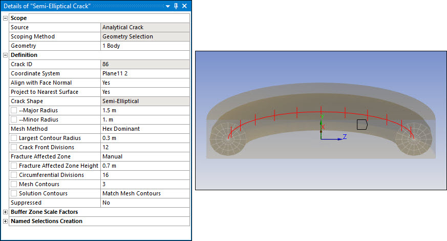
To further define the semi-elliptical crack, use the following controls. These controls appear in the Details View of the Semi-Elliptical Crack object. As you specify values for the controls, the image in the Geometry window previews the entered data.
The following figure shows an example of a semi-elliptical crack definition and its corresponding image. The semi-elliptical curve defines the shape of the crack front, as shown by the red line.
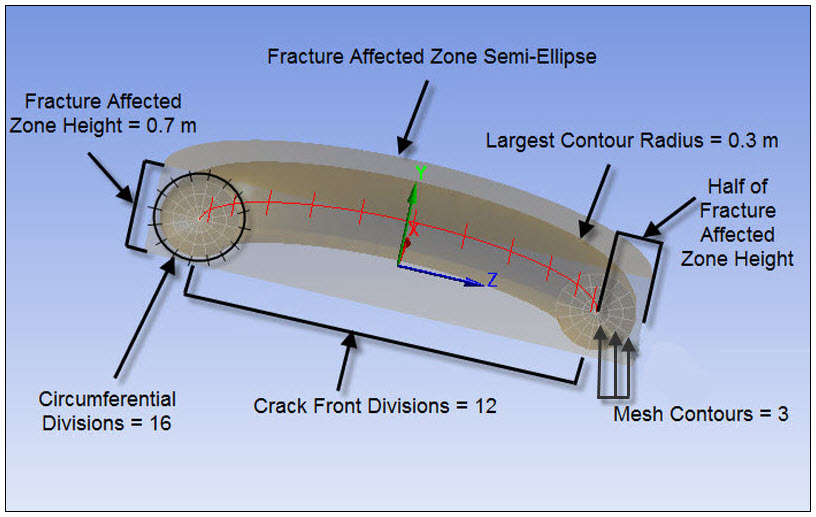
This figure provides a more detailed illustration of the fracture affected zone defined above. Notice that the values shown in the image below correspond to the Details View settings above.
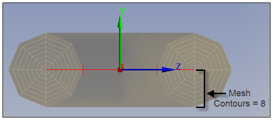
This figure shows the detail of a crack for which Mesh Contours is set to 8.
Crack ID: A read-only property that displays a unique system generated identification number ID for the crack object. The application uses this identifier when creating solution identifiers for fracture parameters.
Coordinate System: This property specifies the coordinate system that defines (along with the Align with Face Normal and Project to Nearest Surface properties) the position and orientation of the crack. The Y axis of the specified coordinate system defines the crack plane normal. The coordinate system that you create must be a Cartesian coordinate system (Type property) and its origin cannot lie outside the bounding box of the body scoped to the crack.
Align with Face Normal: This property defines the orientation of the SECrack Coordinate System object by aligning the primary axis of the coordinate system specified in the Coordinate System property to the normal of the nearest surface. The default setting is . Setting this property to excludes the capability of this property.
Project to Nearest Surface: This property defines the origin of the SECrack Coordinate System by projecting the origin of the coordinate system specified in the Coordinate System property to the nearest surface. The default setting is . Setting this property to excludes the capability of this property.
Crack Shape: Read-only and set to Semi-Elliptical.
Major Radius: Specifies the major radius, which defines the size of the crack shape along the Z axis (that is, the width of the crack). Enter a value greater than 0.
Minor Radius: Specifies the minor radius, which defines the size of the crack shape along the X axis (that is, the depth of the crack). Enter a value greater than 0.
Mesh Method: This property enables you to select the mesh method to be used to mesh the semi-elliptical crack. Options include (default) and .
Largest Contour Radius: Specifies the largest contour radius for the crack shape. Enter a value greater than
0.Growth Rate (Mesh Method set to only): Specifies the factor with which the mesh layers will grow along the radius of the crack. Specify a value greater than
1. The default value is1.2. The recommended value is equal to or greater than1.1.Front Element Size (Mesh Method set to only): Specifies the element size for the crack front. The default value is computed using crack length. Specify a value greater than
0.Crack Front Divisions (Mesh Method set to only): Specifies the number of divisions for the crack front. Your entry must be equal to or greater than
3. The default is15.The Geometry window can display only a maximum of 999 crack front divisions, but you can specify a higher value and fracture meshing will respect it.
Fracture Affected Zone (Mesh Method set to only): The fracture affected zone is the region that contains a crack. The Fracture Affected Zone control determines how the fracture affected zone height is defined:
Program Controlled: The software calculates the height, and Fracture Affected Zone Height is read-only. This is the default.
Manual: You enter the height in the Fracture Affected Zone Height field.
Fracture Affected Zone Height (Mesh Method set to only): This value specifies two things: 1) the height of the Fracture Affected Zone, which is in the Y direction of the crack coordinate system; and 2) the distance in totality by which the Fracture Affected Zone is extended in the positive and negative Z direction of the crack coordinate system from the crack front extremities.
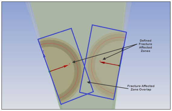
The shape of a Fracture Affected Zone is rectangular, regardless of the shape of the crack. Although buffer zones may overlap, care should be taken when defining multiple cracks that the zones do not overlap, as shown here, or the crack generation will fail.
Circumferential Divisions (Mesh Method set to only): Specifies the number of circumferential divisions for the crack shape. The value you enter must be a multiple of 8, and must be 8 or greater. The default is 8.
The Geometry window can display only a maximum of 360 circumferential divisions, but you can specify a higher value and fracture meshing will respect it.
Mesh Contours: Specifies the number of mesh contours for the crack shape. The value you enter must be 1 or greater. The default is 6.
The Geometry window can display only a maximum of 100 mesh contours, but you can specify a higher value and fracture meshing will respect it.
Solution Contours: Specifies the number of mesh contours for which you want to compute the fracture result parameters. The value you enter must be less than or equal to the value of Mesh Contours, and cannot be greater than 99. By default, the value is Match Mesh Contours, indicating the number of Solution Contours is equal to the number of Mesh Contours. Entering 0 resets the value to Match Mesh Contours.
Suppressed: Toggles suppression of the Semi-Elliptical Crack object. The default is No.
The Semi-Elliptical Crack object is suppressed automatically if the scoped body is suppressed.
Buffer Zone Scale Factors
It controls the size of the buffer zone in the X, Y, and Z directions, relative to the dimensions of the crack. For each scaling parameter, use the slider to set a value from
2to50. The default is2. The maximum dimension among the three directions of the crack is multiplied by the corresponding scale factors to create a buffer zone. When the Mesh Method is , the crack dimensions also include fracture-affected zones.X Scale Factor
Y Scale Factor
Z Scale Factor
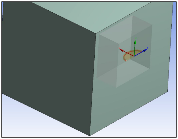
As illustrated here, buffer zone scale factor annotations are not drawn in the negative X direction. That is, half of the cuboid is drawn to depict the buffer zone scale factors, but the half of the cuboid in the negative X direction is not drawn.
The remaining controls pertain to Named Selections that are created automatically when the fracture mesh is generated, as described in Step 6 below. To ensure associativity to the corresponding Semi-Elliptical Crack object, the following default naming convention is used for these Named Selections.
The following naming convention is used for Named Selections for crack objects with the name Semi-Elliptical Crack:
NS_ SECrack _Front
NS_ SECrack _TopFace
NS_ SECrack _BottomFace
NS_ SECrack _Contact1
NS_ SECrack _Target1
For example, for a Semi-Elliptical Crack object named Semi-Elliptical Crack 4, the default names are NS_SECrack 4_Front, NS_SECrack 4_TopFace, NS_SECrack 4_BottomFace, NS_SECrack 4_Contact1, and NS_SECrack 4_Target1.
The Named Selections controls are defined as follows:
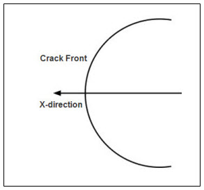
Crack Front Nodes: Identifies the Named Selection that is created automatically for the crack front (NS_SECrack_Front). Contains nodes used for postprocessing of results.
As shown, the crack front is always perpendicular to the X axis.
Crack Faces Nodes: Determines whether Named Selections are created automatically for the crack’s top face and bottom face. These faces are both located in the XZ plane and are discontinuous.
The default setting is On. When set to On, the following additional fields appear:
Top Face Nodes: Identifies the Named Selection that is created automatically for the top face (NS_SECrack_TopFace). This face is discontinuity plane 1. Contains nodes used for applying a pressure to the top face.
Bottom Face Nodes: Identifies the Named Selection that is created automatically for the bottom face (NS_SECrack_BottomFace). This face is discontinuity plane 2. Contains nodes used for applying a pressure to the bottom face.
Contact Pairs Nodes (Mesh Method set to only): Determines whether Named Selections are created automatically for the contact and target faces of the contact pair. The default is Off. If On, the additional fields listed below appear. Fracture meshing creates contact pair 1 between the fracture affected zone and the buffer zone.
Contact 1 Nodes: Identifies the Named Selection that is created automatically for contact face 1 (NS_SECrack_Contact1). Contains nodes located on the contact face. The contact nodes are selected at the interface from the buffer zone of the base mesh.
Target 1 Nodes: Identifies the Named Selection that is created automatically for target face 1 (NS_SECrack_Target1). Contains nodes located on the target face. The target nodes are selected at the interface from the fracture affected zone of the hex dominant mesh.
Select the Fracture object or Semi-Elliptical Crack object in the Tree Outline, right-click, and select Generate All Crack Meshes.
When the fracture mesh is generated, the requested Named Selections are inserted into the Tree Outline under the Semi-Elliptical Crack object with which they are associated.
Click Show Mesh on the Graphics Toolbar to display the fracture mesh.