


The steps for defining an Arbitrary crack are presented here.
Select the Model object in the Tree Outline.
Insert a Fracture object into the tree Outline by right-clicking on the Model object and selecting Insert > Fracture from the context menu. Alternatively, select the Fracture option from the Define group on the Model Context Tab.
Note: Only one Fracture object is valid per Model.
Insert an Arbitrary Crack object into the tree by right-clicking on the Fracture object and selecting Insert > Arbitrary Crack from the context menu. Alternatively, click the Arbitrary Crack option from the Crack group of the Fracture Context Tab.
An Arbitrary Crack definition must always be scoped to a single solid body. Use the Body selection filter to pick a body in the Geometry window, click the Geometry field in the Details View, and then click Apply.
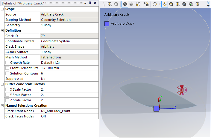
To further define the Arbitrary Crack, use the following Details pane properties. As you specify values for the properties, the image in the Geometry window previews the entered data. An example of Arbitrary crack definition, including an image of the crack on the model, is illustrated below.
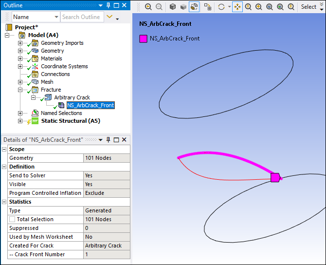
As defined by the application generated Named Selection, the portion of the curve located inside the cylinder, including the intersection points, defines the shape of the crack front.
Crack ID: A read-only property that displays a unique system generated identification number ID for the crack object. The application uses this identifier when creating solution identifiers for fracture parameters.
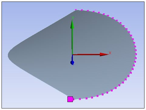
Coordinate System: This property specifies the coordinate system that defines the orientation of the crack. The Y axis of the specified coordinate system must be directed towards the normal of the crack's top face.
Crack Shape: Read-only property set to Arbitrary.
Crack Surface: You use this property to specify the surface body to be used as the crack surface. This surface body can be on a surface or embedded within the solid body, or it can intersect with the free surfaces of the solid body. This generates an arbitrary crack that is a surface crack, shaped as an ellipse, a ring, a cylinder, it can be a through-crack that cuts through a solid body, or a corner crack that intersects at multiple corners of the solid body.
Mesh Method: Read-only property set to .
Note: When this crack intersects with the free surfaces of a solid body, the setting is not supported.
Largest Contour Radius: Specifies the largest contour radius for the crack shape. Enter a value greater than
0. If you specify a Front Element Size value, this property is not applicable.Growth Rate Specifies the factor with which the mesh layers will grow along the radius of the crack. Specify a value greater than
1. The default value is1.2. The recommended value is equal to or greater than1.1.Front Element Size Specifies the element size for the crack front. The default value is computed using the values of the Largest Contour Radius property and the Growth Rate property.
Mesh Contours: Specifies the number of mesh contours for the crack shape. Your entry must be equal to or greater than
1. The default value is6. If you specify a Front Element Size value, this property is not applicable.The Geometry window can display only a maximum of 100 mesh contours, but you can specify a higher value and fracture meshing will respect it.
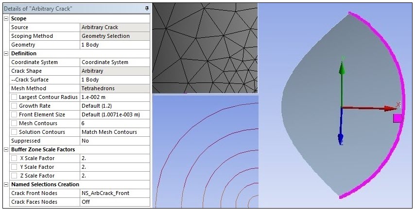
Note: You can use the graphics preview of an arbitrary crack to examine the relative effect of the mesh parameters on the generated crack mesh. The first mesh contour's radius shown as a bull's-eye view in Geometry window is equal to specified Front Element Size. The mesh contours grow at the rate of the specified Growth Rate value as seen in the image. Also, the generated crack mesh is an unstructured tetrahedron mesh and may not accurately compare to all the mesh parameters seen in the Geometry window.
Solution Contours: Specifies the number of mesh contours for which you want to compute the fracture result parameters. The value you enter must be less than or equal to the value of the Mesh Contours property, and cannot be greater than
99. By default, the value is set to Match Mesh Contours, indicating that the number of Solution Contours is equal to the number of Mesh Contours. Entering 0 resets the value to Match Mesh Contours.Suppressed: Toggles suppression of the Arbitrary Crack object. The default is No.
The Arbitrary Crack object is suppressed automatically if both the scoped body and scoped crack surface are suppressed.
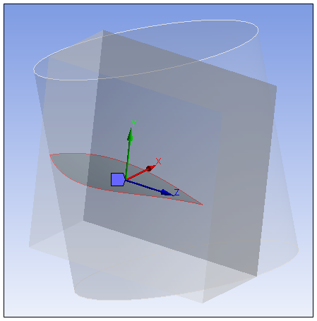
Buffer Zone Scale Factors: Control the size of the buffer zone in the X, Y, and Z directions, relative to the crack surface geometry dimensions. For each scaling parameter, use the slider to set a value from
2to50. The default value is2. The maximum dimension among the three dimensions of the crack surface geometry is multiplied by the corresponding scale factors to create a buffer zone:X Scale Factor
Y Scale Factor
Z Scale Factor
As illustrated here, buffer zone scale factor annotations are not drawn in the negative X direction. That is, half of the cuboid is drawn to depict the buffer zone scale factors, but the half of the cuboid in the negative X direction is not drawn.
The remaining properties pertain to Named Selections that are created automatically when the fracture mesh is generated, as described in Step 6 below. To ensure associativity to the corresponding Arbitrary Crack object, the following default naming convention is used for these Named Selections.
The following naming convention is used for Named Selections for crack objects with the name Arbitrary Crack:
NS_ ArbCrack _Front
NS_ ArbCrack _TopFace
NS_ ArbCrack _BottomFace
For example, for an Arbitrary Crack object named Arbitrary Crack 4, the default names are NS_ArbCrack 4_Front, NS_ArbCrack 4_TopFace, and NS_ArbCrack 4_BottomFace.
The Named Selections controls are defined as follows:
Crack Front Nodes: Identifies the Named Selection that is created automatically for the crack front (NS_ArbCrack_Front). Contains nodes used for postprocessing of fracture parameter results.
As shown, the X axis helps determine the extension direction of the crack front node.
Important: For cracks with multiple crack fronts, the Crack Front Nodes property, under Named Selection Creation category, only modifies the first crack front name if you have already generated the mesh. However, the application applies the property value to all crack fronts if you are generating the mesh for the first time or if the mesh is re-generated.
Crack Faces Nodes: Determines whether Named Selections are created automatically for the crack’s top face and bottom face. These faces are both located in the XZ plane and are discontinuous.
The default setting is On. When set to On, the following additional fields appear:
Top Face Nodes: Identifies the Named Selection that is created automatically for the top face (NS_ArbCrack_TopFace). This face is discontinuity plane 1. Contains nodes used for applying a pressure to the top face.
Bottom Face Nodes: Identifies the Named Selection that is created automatically for the bottom face (NS_ArbCrack_BottomFace). This face is discontinuity plane 2. Contains nodes used for applying a pressure to the bottom face.
Select the Fracture object or Arbitrary Crack object in the tree Outline, right-click, and select Generate All Crack Meshes.
When the fracture mesh is generated, the requested Named Selections are inserted into the tree Outline under the Arbitrary Crack object with which they are associated.
Click Show Mesh on the Graphics Toolbar to display the fracture mesh.
Note: Mesh near arbitrary crack is projected to facets if the geometry is faceted. Thus, if you see mesh being projected slightly away from the geometry, it might be because of the coarseness of geometry facets.