


This section describes some of the tools that you should try to use when generating and managing contact.
Automatic Contact Generation
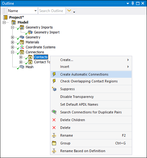
On geometry attach, or when requested, Contact pairs can be automatically detected and generated in Mechanical. Search options also can be set on the Contact folder, and include:
Scoping (search entire assembly or only selected bodies)
Auto Detection Tolerance (see Connection Group Folder Help section)
Topology Types (Face/Face)
Grouping Options
Manual Contact Pairs
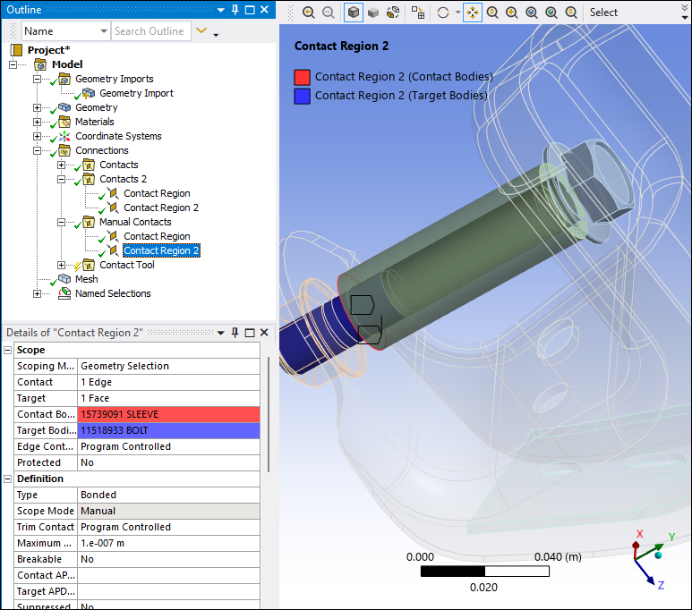
There are times when you need to create contact conditions manually. This could be necessary when a required contact is not detected automatically, such as when a gap exists that is outside of the tolerance, as shown in the example below.
Multiple Contact Folders
Creating multiple contact folders can be beneficial. Multiple folders enable you to:
Create different automatic detection settings on different bodies.
Organize a large numbers of contact regions more efficiently.

Contact Search and Select
To find connections associated with a geometric selection, the context menu (right-click) options.
Worksheet Options
As illustrated below, the connections Worksheet view provides a detailed layout for reviewing all of your contact settings, and includes the capability to:
Sort rows by clicking the column header.
Control the visibility of each column/property using the selections available on the right-click (context) menu.
|
Contact Worksheet |
|

|
|
RMB Menu |
|

|
Body Views
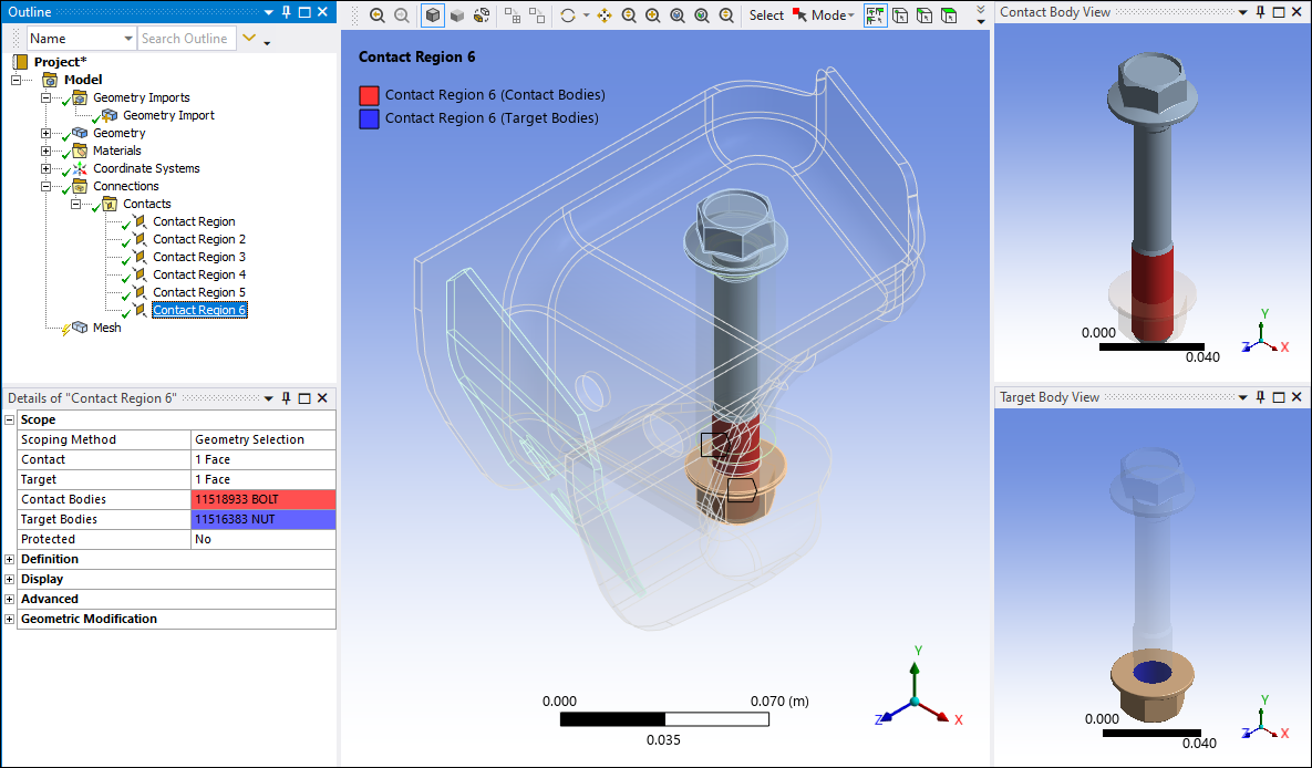
A helpful way to spatially identify a contact, especially when the contact occurs on the interior of your model, is to use the Body Views feature on the Connections Context Tab to display parts in separate auxiliary windows.
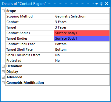
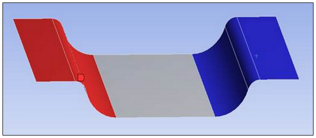
This is the default display option when you select a Contact object, and as illustrated below, the different contact bodies (Contact and Target) have colors codes associated with them in the Details view as well as the graphic windows. This display not only highlights the geometric entities in contact, but displays the bodies of the corresponding part(s).
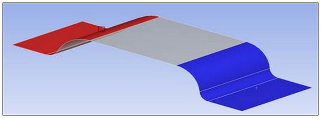
Shell Contact Normal Directions
Contact on shell bodies can only be detected if the direction of the contact is appropriately defined. For example, to model the self-contact when pinching the following shell:
|
Undesirable Normals |
Details View |
|
|
|
|
Desired Normals | |
|
|
Contact Tool
You can use the Contact Tool to quickly learn about the contact status as seen by the solver (before you solve). Initial Information is illustrated below.
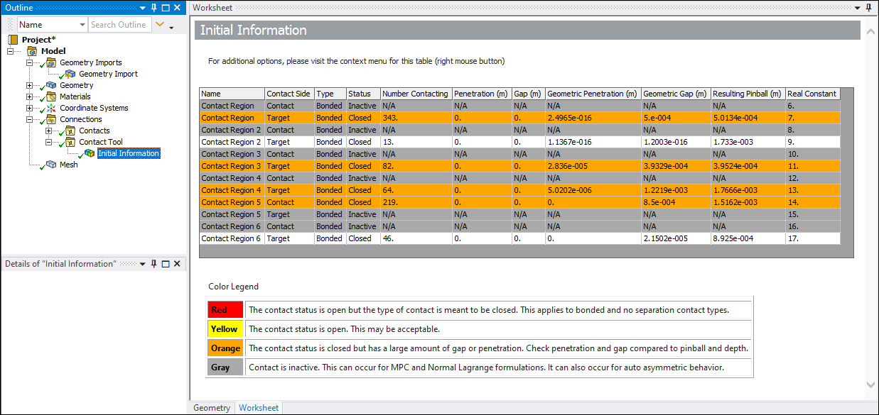
The color coding alerts you to possible issues. And you can calculate contours for results such as Status and Penetration. In addition, you can see:
Contact pairs that are open/closed.
The extent of initial penetration.
Active/Inactive pairs.