


A Path is categorized as a form of construction geometry and is represented as a spatial curve to which you can scope path results. The results are evaluated at discrete points along this curve.
You defined a Path using the following methods:
- By Start and End Point
These points can be specified directly or can be calculated from the entry and exit point (intersections) of the positive X-axis of a coordinate system through a mesh. The path may be a straight line segment or a curve depending on the type of coordinate system (Cartesian or Cylindrical). You can control the discretization by specifying the number of sampling points, and these will be evenly distributed along the path up to a limit of 200.
Note: Paths defined in this manner will only be mapped onto solid or surface bodies. If you wish to apply a path to a line body you must define the path by an edge (as described below).
- Edge
The discretization will include all nodes in the mesh underlying the edge. Multiple edges may be used but they must be continuous.
Result Graphical Display
For each result scoped to a Path, the Graph Controls category provides an option to display the result in the Graph on X-axis, as a function of Time or with S, the length of the path. Note that Path results have the following restrictions:
They are calculated on solids and surfaces but not on lines.
They can be collected into charts as long as all of the other objects selected for the chart have the same X-axis (Time or S).
You can define a path in the geometry by specifying two points, an edge, or an axis. Before you define a path, you must first add the Path object from the Construction Geometry context toolbar.
You can then define the path using any of the methods presented below.
Application
There are a number of methods to define a Path, including:
Additional options for this feature include:
Defining a Path using Two Points
Using this method you define the path by specifying two points in any of the following ways:
- Define path using the Hit Point Coordinate option:
In the Details, select Two Points in the Path Type list.
Under Start, choose Click to Change in the Location row.
Select the option on the Graphics Toolbar.
As you move the cursor across the model, the coordinates display and update as you reposition the cursor.
Click at the desired start location for the path. A small cross hair appears at this location. You can click again to change the cross hair location.
Click . A "1" symbol displays at the start location. Also, the coordinates of the point display in the Details view. You can change the location by repositioning the cursor, clicking at the new location, and then clicking Click to Change and , or by editing the coordinates in the Details view.
Repeat steps 2 through 5 to define the end point of the path under End in the Details view. A "2" symbol displays at the end location.
Enter the Number of Sampling Points.
- Define path using coordinates:
In the Details view, select Two Points in the Path Type list.
Under Start, enter the X, Y, and Z coordinates for the starting point of the path.
Under End, enter the X, Y, and Z coordinates for the ending point of the path.
Enter the Number of Sampling Points.
- Define Path using vertices, edges, faces, or nodes:
In the Details view, select Two Points in the Path Type list.
Select one or more vertices or nodes, a single edge, or a face where you want to start the path, and then click Apply under Start, Location. An average location is calculated for multiple vertex or node selections.
Select the vertices, nodes, face, or the edge where you want to end the path, and then click Apply under End, Location.
Enter the Number of Sampling Points.
Note: The start and end points need not both be specified using the same procedure of the three presented above. For example, if you specify the start point using the Coordinate toolbar button, you can specify the end point by entering coordinates or by using a vertex, edge, or face. Any combination of the three procedures can be used to specify the points.
Defining a Path using an Edge
This method helps you define a path by selecting an edge. To define a path:
In the Details view, select Edge in the Path Type list.
Specify an edge geometry using Geometry Selection or by specifying an edge-based Named Selection.
Defining a Path from Results Scoped to Edges
In order to help better quantify the variation of a result along a set of edges, path results are available. For a result that is scoped to an edge or multiple contiguous edges, you can convert the scoping to the equivalent Path, by:
Selecting the result object that is scoped to an edge or contiguous edges.
Display the context menu by right-clicking the mouse, and the select .
A Path object is automatically created under the Construction Geometry folder and the Path Type property is set to Edge.
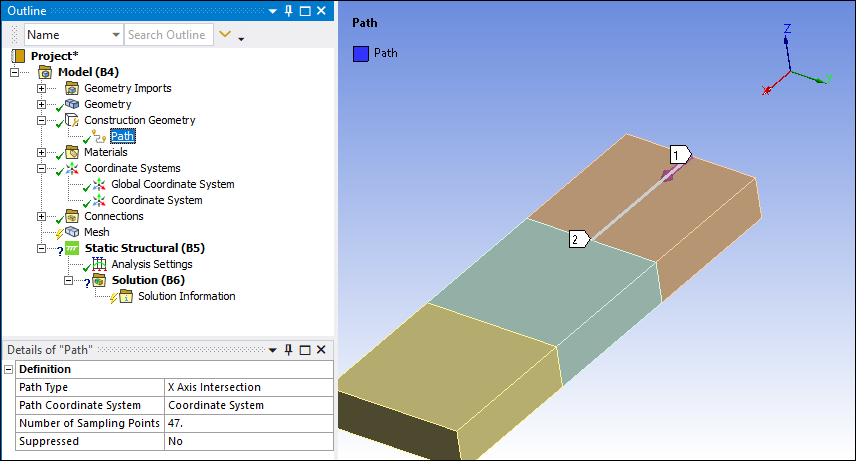
Defining a Path using X Axis Intersection
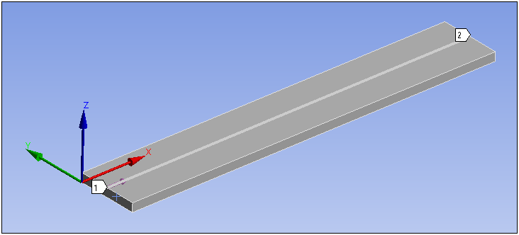
For this option, the application automatically creates the path on the first body the line intersects from the coordinate system origin, as illustrated below. A line is extended along the positive X axis of the selected coordinate system, and the path is created between the first and last points where this line intersects the first body. To create this Path:
Important: When you specify a Path as the scoping for a result, the application re-calculates the path using the mesh instead of geometry. As a result, the locations of path points may vary slightly.
Set the Path Type property to .
Select the desired coordinate system that defines the x-axis using the Path Coordinate System property.
Specify the Number of Sampling Points. The default is value is
47.
Defining a Path from Probe Labels
While reviewing results, you can define a path automatically from two probe labels. To define the path:
Create two probe annotations by choosing the button from the Result Context Tab.
Choose the button from the Graphics Toolbar and select the two probe annotations. (Hold the Ctrl key to select both probe annotations.)
Right-click in the Geometry window and choose from the context menu.
A path is automatically created between the probe annotations. A corresponding Path object is displayed in the tree with a Path Type of Two Points.
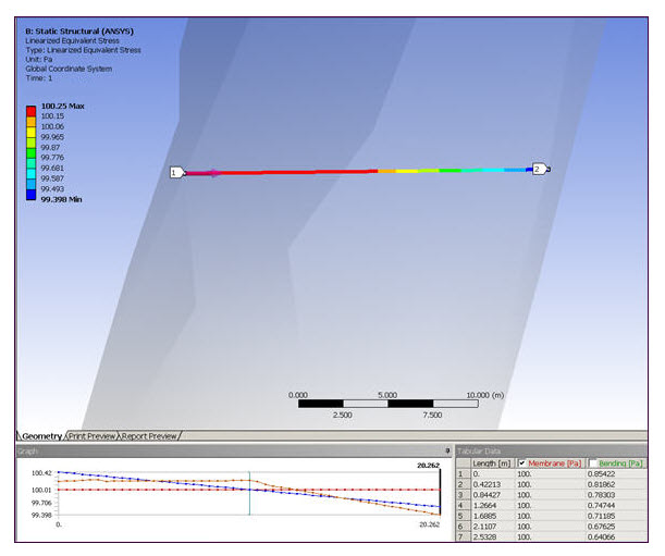
Snap to Mesh Nodes
When solving linearized stresses, the path you define by two points must be contained within the finite element mesh to avoid an error. Because the two points can be derived from the tessellation of the geometric model, the points may be contained within the geometry but may not be contained within the mesh. This is especially true for curved geometry faces. After defining the two points using the Coordinate toolbar button method (see above), you can ensure that the path is contained within the mesh by using the feature. To use the feature, set Show Mesh to Yes in the Details view of the Construction Geometry object in order to see the location of the nodes in the mesh. Then, right-click the Path object and select from the context menu. This action alters the path, as necessary, such that both the start point and end point of the path snap to the closest node in the mesh.
The feature avoids the error and allows the solve to continue provided the path you define does not traverse through any discontinuities in the model, such as a hole. For these cases, even though the feature alters the path endpoints to coincide with the nearest nodes in the mesh, the linearized stress result still fails because the path is defined through the discontinuity.
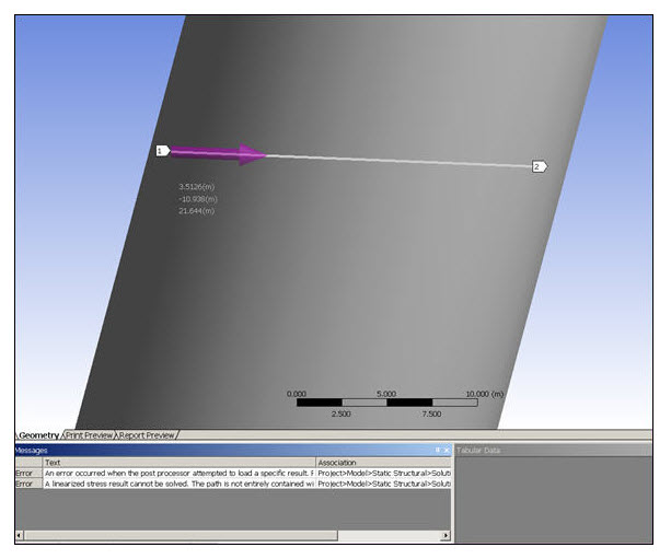
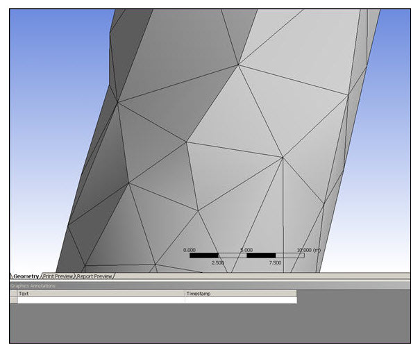
The following pictures illustrate this feature.
Attempt to solve for linearized stress. Path defined within geometric model:
Corresponding mesh used for geometric model, obtained by setting Show Mesh to Yes:
Path contained within mesh after choosing . Solution completes:
Note: If the model is re-meshed after choosing , the feature is not automatically applied to the newly meshed model. You must choose again to alter the path start and end points to the new mesh.
Exporting Path Data
You can export coordinate data for a defined path by clicking the right mouse button on a Path object and choosing from the context menu.