


A Path is categorized as a form of construction geometry that is represented as a spatial curve. Path results are evaluated at discrete points along this curve.
Go to a section topic:
Scoping a Path to a Result
If you have already defined a path, you can view the path results by highlighting the result object, and in the Details, setting Scoping Method to Path, then choosing the name of the particular path that you defined.
Note:
| Path results are not supported for models using periodic symmetry. |
| In Explicit Dynamics models, the path results are not supported for geometries that use an Eulerian reference frame. |
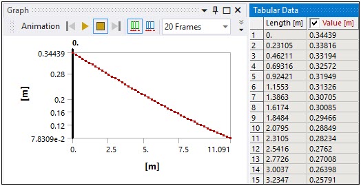
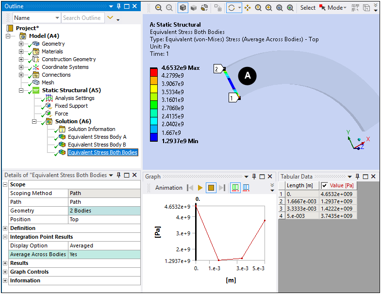
An example path result plot is shown below.
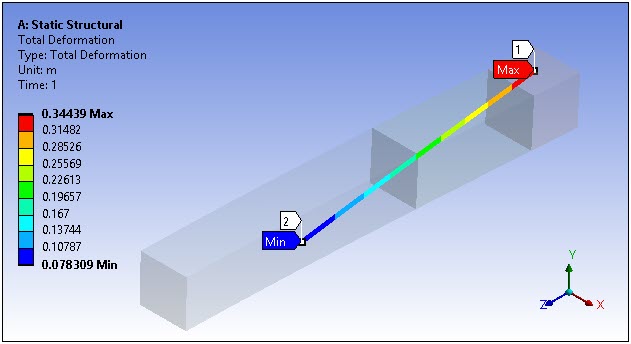
In this example, the Number of Sampling Points for the Path object was set to 47. Results were calculated for each of these 47 points as shown in the Graph below.
Scoping Two Point Path Results
When you define a using two points ( or options), for each point in the Path, Mechanical selects only one body from which to calculate the results. If you scope a Path to multiple bodies, Mechanical calculates the results from the body with the highest identifier as defined in the CAD application. Generally, the part/body with the highest identifier is the one most recently added. No averaging is done for a Path result across bodies, regardless if the setting of the Average Across Bodies property.
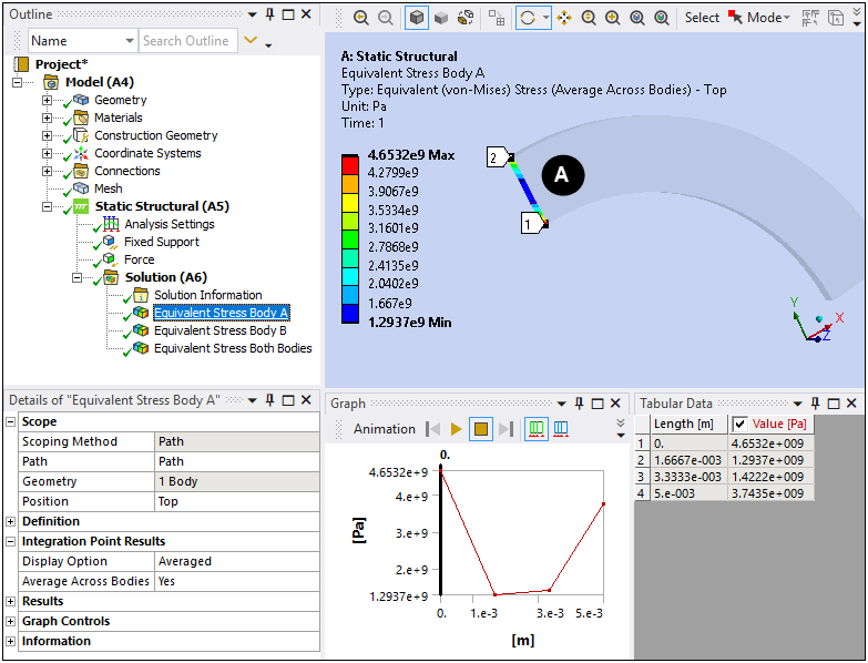
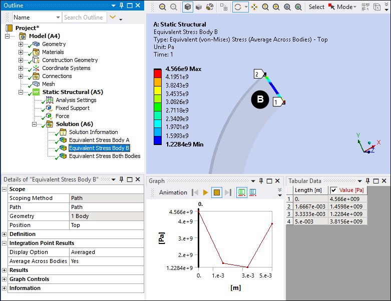
If a Path traverses multiple surface or solid bodies and if a Path point lies on the interface between the distinct bodies, the application only displays the body used to create the result. For example, as illustrated here, a Path is defined by the edge between two surface bodies. Note that both bodies are scoped. However, the result contours on the Path are only based on body A.
In the first two images, a body (A and B) is specified in the Geometry property for the result. Only one body is displayed in the Geometry window. And, note that the stresses for Body A and Body B differ. In the third image, the result is scoped to both bodies. The stresses displayed for this third image match those of Body A because it has the highest identifier and therefore selected by the application by default.
Scoping Edge Path Results
When you define a using the option and the traverses at least one line body, then for element-nodal results, such as stress, scoped to the , each node in the Path collects data from every scoped body and element that touch the node. Therefore, if a result is specified as , all the elements touching a node contribute to the averaged value at that node. If the result is specified as , all the elements touching a node contribute to the contour of the result at that node.
For a defined by the Edge option that does not traverse a line body, no behavior change occurs. The results solve as they would for non-path scoping.
Note: In previous releases, edge-based Paths that traversed at least one line body allowed at most two elements to contribute to a result at any path node.
Understanding Interpolation and Paths
For a given path, Mechanical examines each element in the set of scoped bodies to determine the set of elements which contain a point on the path. A path point may reside on a face of an element, in the interior of an element, or in no element. The set of path points is, in essence, a set of interpolation points.
Assume, for example, that you request a normal x-axis stress result on the path (that is, SX). For a given interpolation point
(x,y,z) lying on the face or residing in the interior of an element, Mechanical finds the natural (or normalized) coordinates of the point within the
element. Mechanical then interpolates the corner values of SX, using the natural coordinates and shape functions, to find a value for
SX at (x,y,z).
See the Interpolation section for additional information.
Important:
If an interpolation point (x, y, z) lies on a face, edge, or a vertex that is shared by multiple elements, the application selects one element only to be used for result calculations. Because the application selects the element, there is no simple method to accurately identify the element selected.
If the result for a path is an element-nodal unaveraged result, the results at the interpolation point are interpolated from the unaveraged nodal stresses of the host element (x, y, z) only. Subsequently, the graph of the unaveraged result may not be smooth or differentiable.