


You can control the relative accuracy of a solution in two ways. You can use the meshing tools to refine the mesh before solving, or you can use convergence tools as part of the solution process to refine solution results on a particular area of the model. This section discusses the latter.
Through its convergence capabilities, the application can fully automate the solution process, internally controlling the level of accuracy for selected results. You can seek approximate results or adapted/converged results. This section explains how to interpret accuracy controls.
Go to a section topic:
Converged Results Control
You can control convergence to a predefined level of error for selected results. In the calculation of stresses, displacements, mode shapes, temperatures, and heat fluxes, the application employs an adaptive solver engine to identify and refine the model in areas that benefit from adaptive refinement. The criteria for convergence is a prescribed percent change in results. The default is 20%. You can change this default using the Convergence setting in the Options dialog box.
Adaptivity (Refinement of Meshes Based on Solutions)
You can continue to refine the mesh based on a specific solution result. When you pick a result (Equivalent Stress, Total Deformation, Total Flux Density, etc.), indicate that you want to converge on this solution. You pick a value and the solution is refined such that the solution value does not change by more than that value.
To add convergence, click the result you added to your solution; for example, Equivalent Stress, Total Deformation, or Total Flux Density. If you want to converge on deformation, right-click Total Deformation and select > . In the Details, you can specify convergence on either the Minimum or Maximum value. Additionally, you can specify the Allowable Change between convergence iterations.
For an adaptive solution, a solution is first performed on the base mesh, and then the elements are queried for their solution information (such as deflection, X-stress, Y-stress, etc.). If the element's results have a high Zienkiewicz-Zhu, or ZZ error (see the Mechanical APDL Theory Reference for more information on adaptivity theory), the element is placed in the queue to be refined. The application then continues to refine the mesh and perform additional solutions. Adaptivity will be more robust if your initial mesh is with tetrahedrons. Adaptive refinement starting from a hex-dominant mesh will automatically result in a re-meshing of the structure with tetrahedrons. The face mesh given to the tet mesher is the initial quad mesh split into triangles. That face mesh is then filled with tetrahedrons so it is recommended that you insert an all tetrahedron mesh method before you start an adaptive solution.
You can control the aggressiveness of the adaptive refinement by adjusting the Refinement Depth setting under Adaptive Mesh Refinement in the Details view of a Solution object. The default value is 2 for structural analyses, and 0 for magnetostatic analyses. The range is from 0 to 3. By default, when adaptive convergence occurs, the program will refine to a depth of 2 elements to help ensure smooth transitions and avoid excessive element distortion for repeated refinement. However, you can adjust this refinement depth to a value of 0 or 1 if for a particular problem, the deep refinement is not required and problem size is a major concern. In general, for mechanical analyses, the default value of 2 is highly recommended. However, you can lower the value if too much refinement is occurring and is overwhelming the solution in terms of size of solution time. If you use a value less than 2, be aware of the following:
Verify that false convergence is not occurring because of too little refinement.
More refinements may be required to achieve the desired tolerance, which may increase the total solution time.
The following pictures show the effects of various settings of Refinement Depth on plots of Total Deformation.
 |
 |
| Base Mesh: No Refinement | Refinement Depth = 0 |
 |
 |
| Refinement Depth = 1 | Refinement Depth = 2 |
For magnetostatic analyses, there are additional settings that allow you to change the percentage of the element selected for adaptive refinement during solution. These settings use an Energy Based percentage and an Error Based percentage. The internal selection process first uses the Energy Based percentage to select the number of elements in the full model that have the highest values of magnetic energy. From this number, it uses the Error Based percentage to select the number of elements with the highest error in the particular body. Magnetic Error results are also available to display on the geometry for verification.
These adaptive refinement settings for magnetostatic analyses are in the Refinement Controls group, located in the Details view of the Solution object, provided you have a Convergence object inserted under any magnetostatic result. An Element Selection setting in this group has the following options:
Program Controlled (default): The percentage of elements selected for adaptive refinement equals the default values of 10% for the Energy Based percentage and 20% for the Error Based percentage.
Manual: The percentage of elements selected for adaptive refinement equals the values you enter in the Energy Based and Error Based fields that appear only when you choose Manual.
For magnetostatic analyses, Directional Force results allow seeking convergence based on Force Summation or Torque as opposed to other results converging on Maximum or Minimum values.
Adaptive Convergence in Multiple Result Sets
You can apply adaptive convergence on multiple result sets that may include different loadings or time points. To do so, create a result for each loading or time point and insert a Convergence object under each result.
The following example shows Total Deformation results at two time points where a Convergence object was inserted under each result.
Ansys Workbench Product Adaptive Solutions
Nearly every Ansys Workbench product result can be calculated to a user-specified accuracy. The specified accuracy is achieved by means of adaptive and iterative analysis, whereby h-adaptive methodology is employed. The h-adaptive method begins with an initial finite element model that is refined over various iterations by replacing coarse elements with finer elements in selected regions of the model. This is effectively a selective remeshing procedure. The criterion for which elements are selected for adaptive refinement depends on geometry and on what Ansys Workbench product results quantities are requested. The result quantity φ, the expected accuracy E (expressed as a percentage), and the region R on the geometry that is being subjected to adaptive analysis may be selected. The user-specified accuracy is achieved when convergence is satisfied as follows:
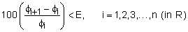
where i denotes the iteration number. It should be clear that results are compared from iteration i to iteration i+1. Iteration in this context includes a full analysis in which h-adaptive meshing and solving are performed.
The Ansys Workbench product uses two different criteria for its adaptive procedures. The first criterion merely identifies the largest elements (LE), which are deleted and replaced with a finer finite element representation. The second employs a Zienkiewicz-Zhu (ZZ) norm for stress in structural analysis and heat flux in thermal analysis.
Table 18.1: Ansys Workbench Product Adaptivity Methods
| Result | Adaptive Criterion |
|---|---|
| Stresses and strains | ZZ norm |
| Structural margins and factors of safety | ZZ norm |
| Fatigue damage and life | ZZ norm |
| Heat flows | ZZ norm |
| Temperatures | ZZ norm |
| Deformations | ZZ norm |
| Mode frequencies | LE |
As mentioned above, geometry plays a role in the Ansys Workbench product adaptive method. In general, accurate results and solutions can be devised for the entire assembly, a part or a collection of parts, or a surface or a collection of surfaces. The user makes the decision as to which region of the geometry applies. If accurate results on a certain surface are desired, the Ansys Workbench product ignores the aforementioned criterion and simply refines all elements on the surfaces that make up the defined region. The reasoning here is that the user restricts the region where accurate results are desired. In addition, there is nothing limiting the user from having multiple accuracy specification. In other words, specified accuracy in a selected region and results with specified accuracy over the entire model can be achieved.
Requirements and Limitations
To use Convergence feature:
To use Convergence, you must set Calculate Stress to Yes under Output Controls in the Analysis Settings details panel. However, you can perform Modal and Buckling Analysis without specifying this option.
Convergence objects inserted under an environment that is referenced by an Initial Condition object or a Thermal Condition load object, will invalidate either of these objects, and not allow a solution to progress.
The Error result that is used for convergence is based on linear stresses and as such may be inaccurate in certain nonlinear analyses, such as when plasticity is active.
When performing an out of process solution asynchronously, wherein the solve may finalize during another Workbench session, the application performs only one maximum refinement loop. As necessary, you must manually perform additional loops. To solve with a single user action, solve synchronously.
Results cannot be converged when you have a Mesh Connection object.
You cannot use Convergence if your system is linked to an upstream or a downstream analysis.
Convergence is not available when you activate either of the following conditions:
Convergence is not supported for:
A model with Layered Sections.
Meshes generated using the MultiZone Quad/Tri, MultiZone Quad, or Patch Independent mesh methods.
Orthotropic materials.
Hyperelastic materials.
Solid shell elements (the SOLSH190 series elements).
If a Periodic Region or Cyclic Region symmetry object is defined.
Notes About Accuracy
Accuracy acceptance:
Low levels of accuracy are acceptable for demonstrations, training, and test runs. Allow for a significant level of uncertainty in interpreting answers. Very low accuracy is never recommended for use in the final validation of any critical design.
Moderate levels of accuracy are acceptable for many noncritical design applications. Moderate levels of accuracy should not be used in a final validation of any critical part.
High levels of accuracy are appropriate for solutions contributing to critical design decisions.
At maximum accuracy, when convergence is not sought, studies of problems with known answers yield the following behaviors and approximated errors:
Less than 20% error for peak stresses and strains, and minimum margins and factors of safety.
Between 5% and 10% error for average (nominal) stresses and elastic strains, and average heat flows.
Between 1% and 5% error for average stress-related displacements and average calculated temperatures.
5% or less error for mode frequencies for a wide range of parts.
When seeking highly accurate, converged Results, more computer time and resources will be required than manual control, except in some cases where the manual preference approaches highest accuracy.
Given the flexible nature of the solver engine, it is impossible to explicitly quantify the effect of a particular accuracy selection on the calculation of results for an arbitrary problem. Accuracy is related only to the representation of geometry. Increasing the accuracy preference will not make the material definition or environmental conditions more accurate. However, specified converged results are nearly as accurate as the percentage criteria.
Critical components should always be analyzed by an experienced engineer or analyst prior to final acceptance.