You use the Solution Combination object/feature to combine load cases, called "base cases" in the application, to generate results that display the effects of the combination of the load cases. The application supports two combination methods:
Multiple: You use this method to combine (sum) multiple base cases.
Envelope: You use this method to display the highest (maximum) or lowest (minimum) result values, among the chosen base cases, at each node/element.
Go to a section topic:
Important: Review the next section, Solution Combination Process Requirements and Conditions, to ensure your understanding of the feature's operations.
Supported Analysis Types
This feature supports the combination of the following analysis types:
Harmonic Response
Explicit Dynamics
Random Vibration
Response Spectrum
Static Structural
Transient Structural
Define Solution Combination
Define Simulation
Define your environments and solve the simulation.
Specify Object
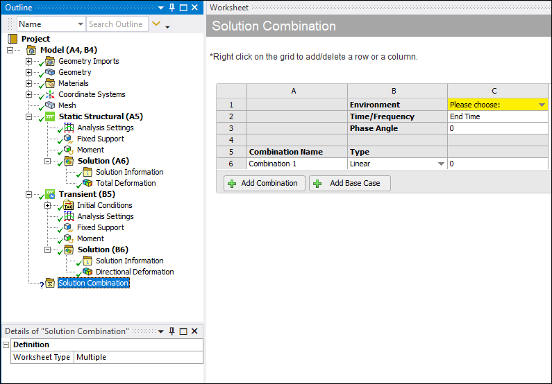
From the Model object, either select the Solution Combination option on the Model Context tab. You can also right-click the Model object or in the Geometry window and select Insert > Solution Combination. The object is inserted and the Worksheet displays.
Specify a combination method using the Worksheet Type property. Options include (default) and .
Define Base Cases
Select one of the following procedures based on the specified method.
Multiple Method
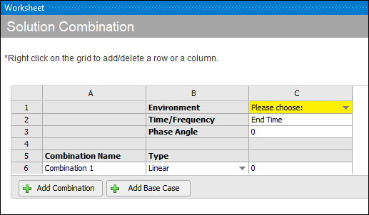
As illustrated below, the application inserts a base case (C column) by default. The Environment setting is not specified by default (yellow highlight). To add additional base cases, select the Add Base Case button or use the available context (right-click) menu.
You define a base case using the following fields:
Environment: Select the desired input environment from the drop-down menu. Supported environments include: Harmonic Response, Random Vibration, Response Spectrum, Static Structural, and Transient Structural.
Time/Frequency: Enter the time step for the base case (for Static and Transient analyses) or the Frequency (for Harmonic Response analysis).
Phase Angle: Enter a phase angle for the base case (for Harmonic Response analysis only)
Note: Time is always defined in seconds. Frequency is always defined in Hz. And Phase Angle is always defined in degrees. No other units or conversions are supported for the Solution Combination Worksheet.
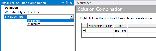
Envelope Method
When you select the method, you need to also specify the Envelope Type property. Options include , , , and .
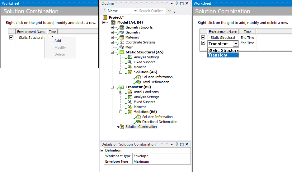
Select environments from the Environment Name drop-down list in the worksheet. A worksheet includes one row by default. Right-click in the worksheet to display the context menu to ( or ) rows.
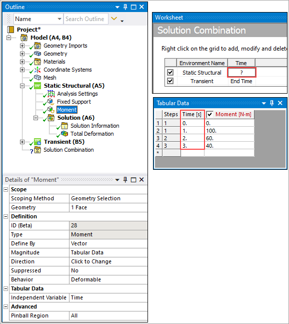
Specify a desired load step for the environment in the Time column. The following example shows the available times (for each Step) for the Moment load in the structural environment. You select from these time values. The default entry is equal to the last load step. You can also enter the specific last step (3 below). You can return the setting to "End Time" by entering 0 (zero) in the time field.
Define Load Combinations (Multiple Method)
When using the method, the application inserts a Combination by default ("Combination 1"), as illustrated below. To add additional Combinations, select the Add Combination button or use the available context (right-click) menu.

You define a Combination using the following fields:
Name (optional): This field defaults to Combination 1, 2, 3, etc.
Type: Specify you combination as either (default) or . For these options:
: Simple addition after multiplying the coefficients with the base results.
: Square Root of the sum of squares (SRSS) after multiplying the coefficients with the base results.
Coefficient: Enter the coefficient or scale factor that you’ll multiply the corresponding base case by.
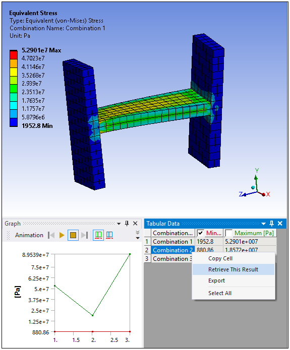
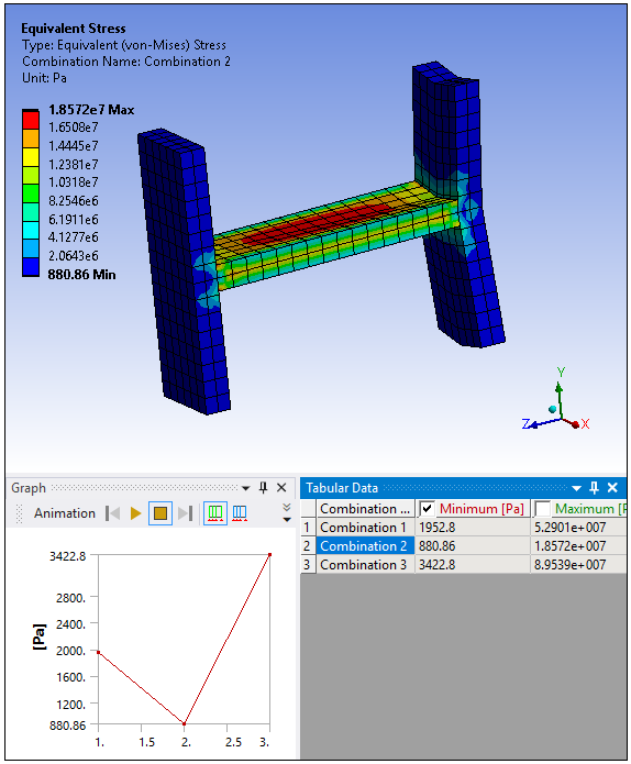
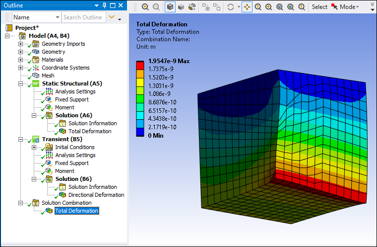
Specify a desired result or results and solve the analysis. You need at least one result. When you solve, the base cases are evaluated and the result provides contours of the combined environments. An example of a result using the method is shown below. It displays all of the highest or the lowest values (minimums or maximums) from each environment.
Import/Export Worksheet
Using the Export option of the Solution Combination Worksheet, you can save the settings that you create as a Comma Separated Value (.csv) file. Using the Import option, you can import these saved files into an analysis.
Interpreting Worksheet Content
Using the Worksheet, you can set up as many combinations as you wish and define different coefficients and input base cases.
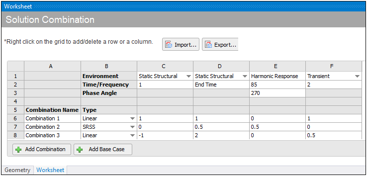
You interpret the base cases (columns) as:
Base Case C: Results from Static Structural environment at Time Step .
Base Case D: Results from Static Structural environment at .
Base Case E: Results from Harmonic Response environment with a Frequency of 85 Hz and a Phase Angle of 270°.
Base Case F: Results from Transient environment at Time Step .
You interpret the Combinations (rows) as:
Combination 1 (Linear): (1×C) + (1×D) + (1×F)
Combination 2 (SRSS): sqrt( (0.5×D)2 + (0.5×E)2)
Combination 3 (Linear): (-1×C) + (2×D) + (0.5×F)
Supported Result Types
|
Once you define Worksheet content, you can define results under the Solution Combination object. Supported results include: | |
|
|
|
|
Note: When using a Fatigue Tool with Solution Combination, the desired combination is selected using the Combination property on the Fatigue Tool. All results added underneath the Fatigue Tool respect this selection. | |
Examining Results
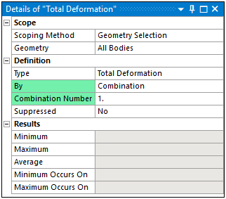
Even though the Solution Combination object enables you to define and solve multiple combinations, you can only view the contour results for a single combination. However, you can select the combination for which you wish to view the results. For the supported result types, the By property in the Details view enables you to specify all combinations or you can specify a specific combination (as well as the additional options described below). You can also select a desired combination from Tabular Data.
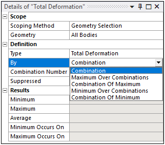
- Using the Options of the By Property
The By property includes the following options:
Combination (default): For this setting, there is an associated property: Combination Number. Using the Combination Number property, and based on the combinations defined in the Worksheet, you can specify a desired Combination for result evaluation. The default setting for the Combination Number property is (last result set).
Note: For the Fatigue Tool, the By property is not available. Only the Combination Number property is available, enabling you to specify a desired Combination.
/: Each node, element, or sample point is swept through the Combinations to find its maximum result. Either the result itself is reported or the Combination at which the peak occurred is reported.
/: Each node, element, or sample point is swept through the Combinations to find its minimum result. Either the result itself is reported or the Combination at which the minimum occurred is reported.
- Using Tabular Data
The Tabular Data window displays a row for each combination defined in the Worksheet. Each row corresponds to a defined combination so you can right-click a row and select the option to view the contour for the desired combination.