


Batch Connections will be deprecated in future releases. Use Automatic (PrimeMesh) Method instead of Batch Connections.
Batch Connections are used for achieving connections in structures made of sheets and beams. Batch Connections uses Connect to connect the beams and shells. Batch Connections uses Repair Topology to defeature the model at mesh level. When Batch Connections is enabled, a fast quad shell meshing algorithm is used to provide high quality mesh on Sheet bodies. This algorithm does not support all Mesh Controls as explained in the Limitations section.
Note: All legacy databases saved with Mesh Based Connection set to Yes will resume with Connect control scoped to the entire assembly.
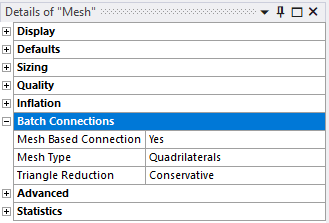
Mesh Based Connection: Activates mesh based connection. The default value is No. When set to Yes, the following options are available:
Mesh Type: Allows you to select the type of mesh to be used for meshing. The mesh types available are Triangles and Quadrilaterals.
Triangle Reduction: Allows you to reduce the triangular elements while meshing. The available options are None, Conservative, Aggressive. The default option is Conservative. Conservative moves the triangles near to the boundary nodes or edges away from the boundary and then reduces the triangles on the whole body. Aggressive moves the interior triangles and the boundary triangles to form pair of connecting triangles and then reduces the triangles on the whole body. Hence, Aggressive reduces more triangles than Conservative.
Note: Aggressive may reduce the quality of the mesh while removing the triangles.
When you select Quality in Batch Connections, you have the following options:
Check Mesh Quality : The default value for Check Mesh Quality is Yes.
Error Limits : Allows you to select two options. They are:
When you select Advanced, the following option is available:
Local Controls in Batch Connections
Batch Connections support local controls. The local controls supported are:
Sizing
Local Sizing controls are supported in Batch Connections. Sizing controls can be applied to edges and faces.
Face Sizing allows you to set the Type as only Element Size. It supports only uniform size functions.
Edge Sizing allows both Element size and Number of Divisions to be set.
For both Face Sizing and Edge Sizing, the default value for Element size is same as the Global Element Size.
Note: Local sizing controls on vertex and body are not supported in Batch Connections.
When you select Sizing in Batch Connections, the following options are available:
Growth Rate: The default value for Growth Rate is 1.2.
Capture Curvature : The default value is No. When the Capture Curvature is set to Yes, the following options are available:
Capture Proximity : The default value is No. When the Capture Proximity is set to Yes, the following options are available:
When Batch Connections is set to Yes, right-click the Mesh folder, click Insert > Mapped Meshing. You can select the faces and click Mapped Meshing to create meshes of the given Element Size.
Best Practices
The recommended inputs for batch connections are as follows:
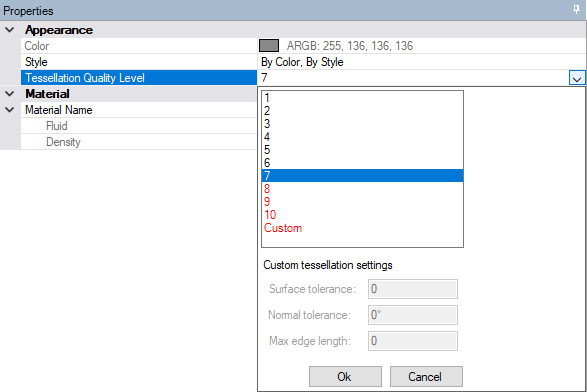
Set the facet quality to 7 before importing model into Mechanical. You can set the facet quality in SpaceClaim by navigating through . The facet quality in DesignModeler can be set by navigating through .
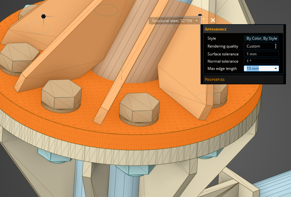
For bodies with large cylindrical faces, a facet quality of 10 may be required for adequate geometric representation during meshing. To avoid rendering the whole model with this value, you can set this value on each body using Body Properties in SpaceClaim or under Appearance in Discovery.
In SpaceClaim, DesignModeler or in other upstream CAD package, Extend operation should be performed. The largest connection gap to be resolved should be smaller than the specified Element size.
Remove overhangs in upstream CAD. Overhangs are small penetrations between two surfaces. When unresolved overhangs can lead to mesh failure or mesh quality issues.
Imprinting edges or performing share topology at CAD level is not recommended. If CAD model has edges already imprinted, then use Virtual Topology to remove them.
If the model has faces with missing facets, then you should fix them in upstream CAD.
The suggested general connection strategy is for clean models that do not have much difference between the smallest and the largest gap to be connected across. The best practices to follow while connecting two entities are as follows:
Find the smallest and largest gap between the entities to be connected.
Define a list of connection tolerance such that the smallest gap is less than the smallest connection tolerance and the largest connection tolerance is greater than the largest gap.
Worksheet is recommended to resolve large gaps rather than using large connection tolerance globally. Define named selection on the entities which requires large tolerance to be connected. Then use this named selection in the worksheet as a step.
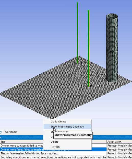
Check for any warning message on unconnected edges reported during meshing.
Right-click the warning message and select Show Problematic Geometry. Use model Walk to analyze the unconnected regions.
Create named selections on unconnected entities.
Activate mesh Worksheet.
Add a step in the Worksheet and scope the created named selection.
Add a step for All Bodies with connection tolerance(s) used previously as global tolerance(s).
Remember the following while performing Batch Connections:
The gap size between the entities to be connected must be smaller than the Element Size. For example, if the biggest gap size to be resolved is 1 mm then the element size must be greater than 1 mm.
Faces (width) and edges (length) of the connected entities below the connection tolerance(s) are defeatured.
Mesh is not associated with defeatured entities (edge, face, body/part).
Mesh is not associated with vertices.
In Batch Connections, the Sheet Loop Removal only works if the connection is made through the Connect control.
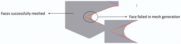
In case of quadrilateral mesh failure, triangle mesh is generated with a warning message displayed.
Right-click the warning message and select Show Problematic Topology to display the bodies on which triangle mesh was generated.
If triangle mesh also fails, then the mesh failure is reported and CAD facets will be displayed.
Limitations
The limitations of Batch Connections are as follows:
Overlapping beams are not supported. Mesh in the overlapping portion of the beams will be assigned to either one of the involved beams.
Mapped Meshing does not support mapping of annular region.
Weld and Mapped control override all other sizing and local control settings.
Batch Connections does not support multi-body parts which includes solid body parts.
Batch Connections does not create conformal meshes between solids.
Batch Connections does not support Layered Tetrahedrons Method.
Batch Connections does not support global Defeature Size, when Mesh Defeaturing is set to Yes in the Sizing option. In Batch Connections, you must use Repair Topology to defeature the geometry. Also, in Repair Topology set Repair Thin Faces Options and Repair Short Edges Options to Yes for automatically repairing short edges and thin faces.
Batch Connections does not support Inflation control, Match control, Pinch control, Adaptive Sizing, BOI Size, Vertex Size (Sphere of Influence).
Batch Connections does not support quality targets provided to the mesher.
Ease of Use Features
When an error or warning such as unconnected edges or mesh failure occurs, you can right-click the corresponding message and select Show Problematic Geometry to highlight the location at which error occurred in the model.
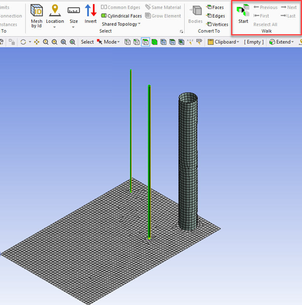
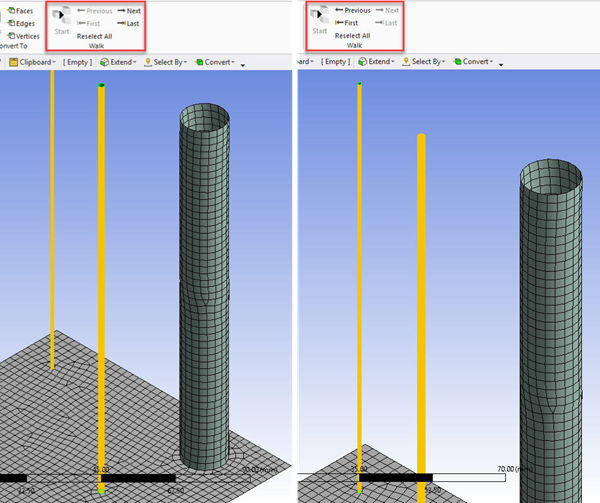
You can click Selections tab in the ribbon and click Start in Walk group to walk through the error locations. You can use Next to walk to the next location. You can click Previous to go back to the previous error location.
You can view the unconnected faces after meshing. To view the unconnected faces, right-click the Geometry window. Select Diagnostics > Find Unconnected Faces. The unconnected faces get highlighted in the model.
When entities scoped to Named Selection with Protected set to Yes are modified while performing batch connections, you will receive a warning message.