


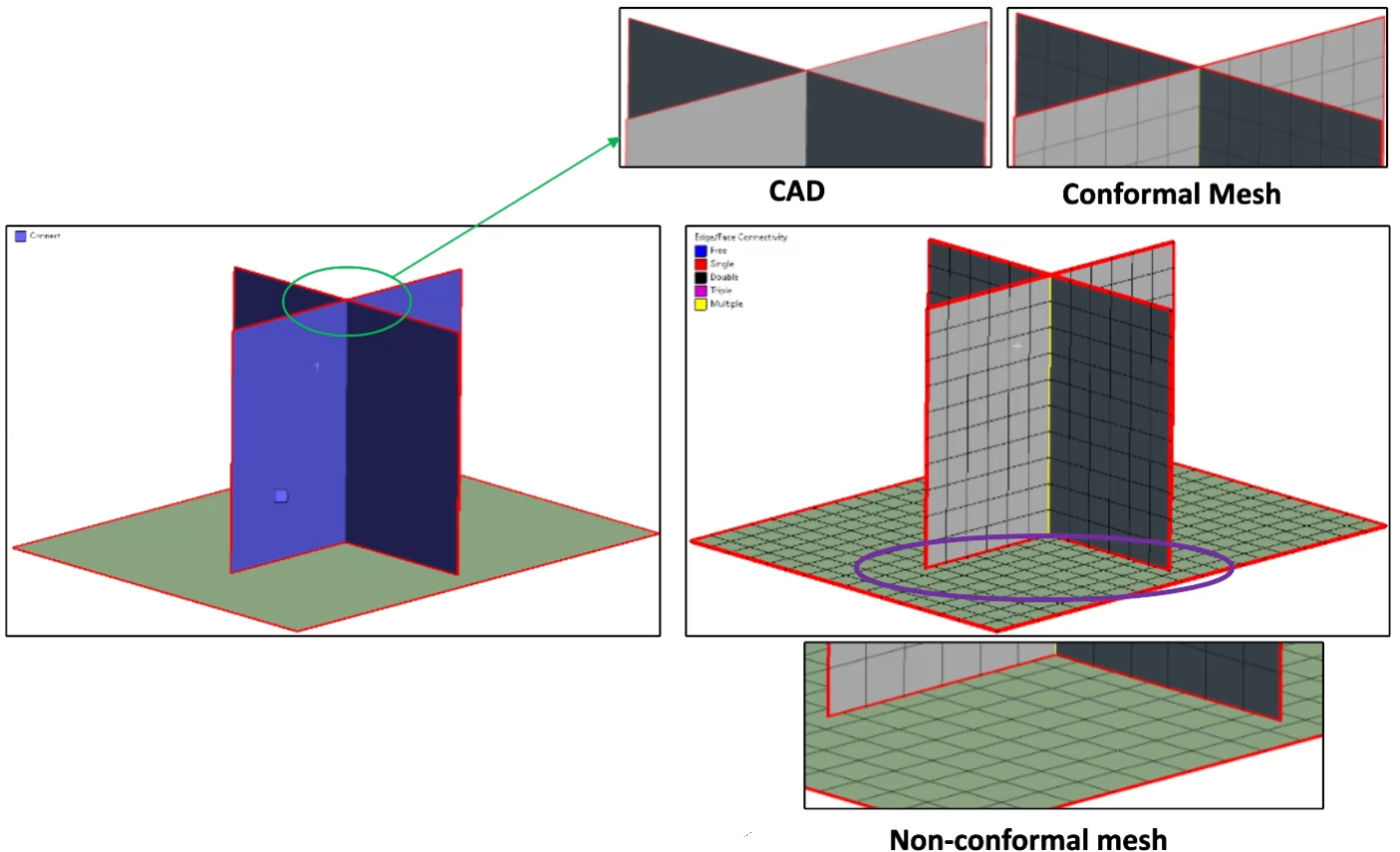
Connect control allows you to create conformal mesh between the selected entities.
All Connect bodies should be scoped under Automatic (PrimeMesh) method. If not, scope the bodies under Automatic (PrimeMesh) to perform Connect operation.
To access Connect control, right-click Mesh object and click Insert > Connect. When you click Connect, the Details view displays the Connect options.
Note:
Connect control does not support scoping to solid entities.
All legacy databases saved with Batch Connections will resume with Connect control.
Scope
Scoping Method: Allows you to select Geometry or Named Selection for scoping.
Use Worksheet: Allows you to scope using worksheet when set to Yes. The default value is No. When Use Worksheet is set to Yes, the connections are made using worksheet.
Connections can also be performed using Worksheet. Worksheet allows you to define the order in which connections are performed and allows you to define varying connection parameters. Worksheet is context sensitive. To perform connections using Worksheet, you must be in the Mesh folder. Click Worksheet in Tools under the Home tab to open the Worksheet.
Note: You can activate, setup and visualize mesh worksheet only from the Mesh folder.
Worksheet allows you to scope named selections. Named selections can either be body based or face based. For each step you can change connection option and specify connection tolerance(s). The available connection options are:
All to All: Connects all possible entities in the scope during the connection process. When All to All is selected, sliver faces and short edges below the connection tolerance value are removed as a part of the connection process.
Free to All: Connects only unconnected edges to rest of the entities in the scope.
Free to Free: Connects only unconnected edges in the scope.
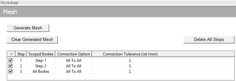
The steps involved in Worksheet based connection are as follows:
Right- click the Worksheet.
Click Add to add a step.
Specify scope defined by named selection from the drop-down list in the Scoped Bodies field. All Bodies is a named selection available by default.
Select the Connection Option.
Specify connection tolerance or list of tolerances for the step. The connection tolerance(s) behaves same as global connection tolerance and list of tolerance.
Add as many steps as required for the connection.
When Generate Mesh is clicked connections are established in the sequence defined in the worksheet. The mesh is generated after all the connections are made.
Note: All Bodies is available by default under scoped bodies in the Worksheet. This named selection is scoped to all bodies in the assembly.
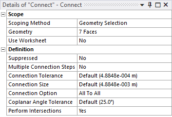
Definition
Suppressed: Allows you to suppress the Connect control. The default value is No. When Suppressed is set to Yes, the Active field displays the status of the Connect control. The Active field is read-only.
Multiple Connection Steps: Allows you to provide multiple values for connection tolerance. The default value is No. When you set Multiple Connection Steps to No, Connection Tolerance field is available to provide the tolerance value for connection. When you set the Multiple Connection Steps to Yes, the Connection Tolerance List is available to provide multiple values for connection tolerance. You can specify any number of connection tolerance values separated by a space. The first value in Connection Tolerance List performs face to face intersections, short edge removal, thin face removal and so on. From the second tolerance value onwards only the unconnected (free) edges are considered for performing connections.
Connection Size: Defines the size with which you discretize the edges before connecting them. By default, the connection size is same as Element Size.
Connection Option: Allows you to select the connect options. The available connection options are All to All, Free to All, Free to Free. For more details, check Connections Using Worksheet
Coplanar Angle Tolerance: Checks whether the two faces to be connected are in the same plane or not. When the faces are in the same plane, intersection is not performed. The value of Coplanar Angle Tolerance is in degrees.
Perform Intersections: Allows you to skip intersection while connecting the selected entities. The default value is Yes.
Note: When you use Connect and Mesh Selected Entities on legacy files which have partially saved mesh, the previously saved mesh gets cleared. You may have to regenerate mesh for the entire model.