


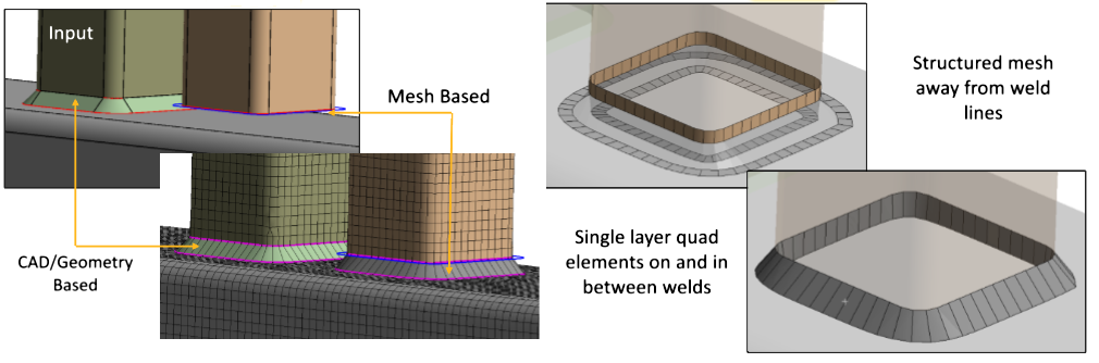
Weld control allows you to create weld bodies and, or generate layers of quad elements on the weld faces (angled and normal faces), in between the angled and normal faces and on the faces that are welded together along the edges shared with the angled and normal faces. When you select Source as Mesh and Create using options like Curves, Curves and Bodies or Curves and Faces, angled and normal faces are created during meshing using defined Weld Curve. The faces are associated to a weld body that is created during meshing. The weld body is available under the Geometry tree object. The weld body name is same as that of the Weld control. One weld body gets created per Weld Curve. Weld supports coincident welds and solid shell welds. In Files > Options > Meshing, when Solid-Shell Weld – Shared Nodes is No under Meshing, creates non conformal mesh with contacts between the shell and the weld bodies. When Solid-Shell Weld – Shared Nodes is Yes, creates conformal mesh without contacts between the shell and the weld bodies. The default value is No.
All Weld bodies should be scoped under Automatic (PrimeMesh) method. If not, scope the bodies under Automatic (PrimeMesh) to perform Weld operation.
Note: Weld bodies created at the mesh level are deleted, when the following occurs:
Mesh is cleared.
Geometry is updated.
You can access the weld control as follows:
On the Tree Outline, click Mesh object.
Right-click the Mesh object in the Tree Outline.
Select Insert > Weld.
Also, you can access Weld from Mesh Context tab when you click Mesh object on the Tree Outline.
When you have a defined Weld object on the Tree, you can right-click Mesh and select Export... > Weld Definition File to write the FE-Safe weld definition files at the provided location.
Weld Details view has the following options:
Scope
Scoping Method: You can use Geometry Selection or Named Selections for scoping. The default value is Geometry Selection. Scoping Method is not available only when the Create Using is set to Curves.
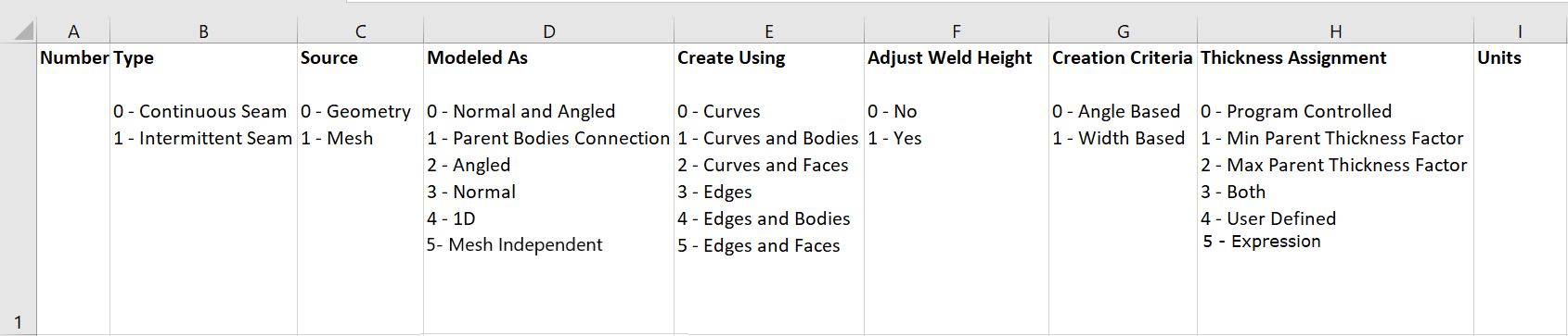
Type: Allows you to select the type of weld control. The available types are:
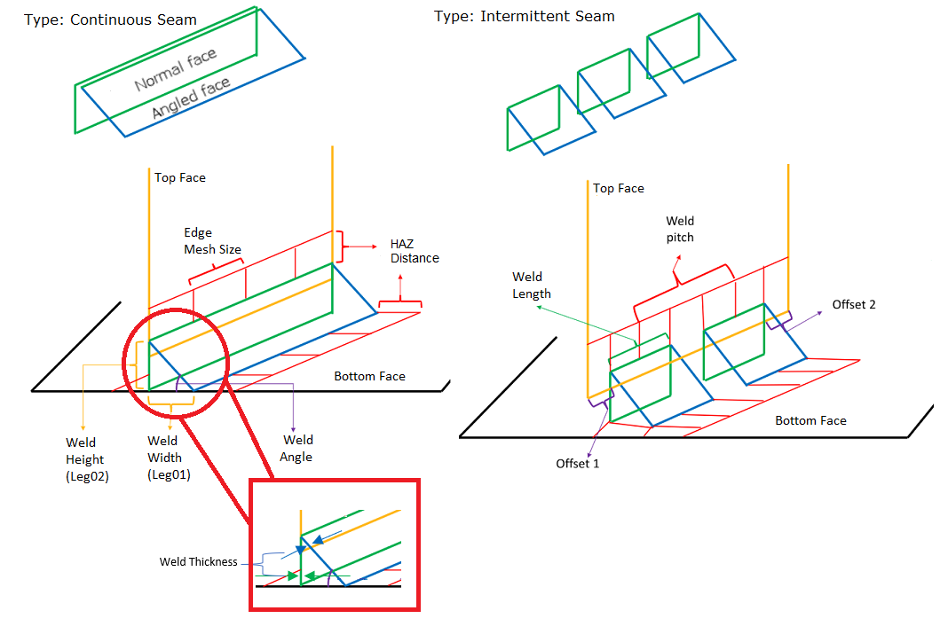
Continuous Seam: Allows you to perform continuous welding.
Intermittent Seam: Allows you to perform discontinuous welding. When you select Type as Intermittent Seam, the Source is Mesh by default and is a read only field.
Note: Intermittent Seam modeled as Mesh Independent is treated as Continuous Seam as it is in contact with solids.
Source: Allows you to select Geometry or Mesh for welding. Source represents where the weld faces are modeled. You can select Geometry, for weld faces created in CAD. You can select Mesh, when the weld entities are to be created during mesh generation.
Modeled As: Allows you to choose or define how weld entities are modeled. When the Source is Geometry and Type is Continuous Seam, you need to define what the weld faces represent. The available options are:
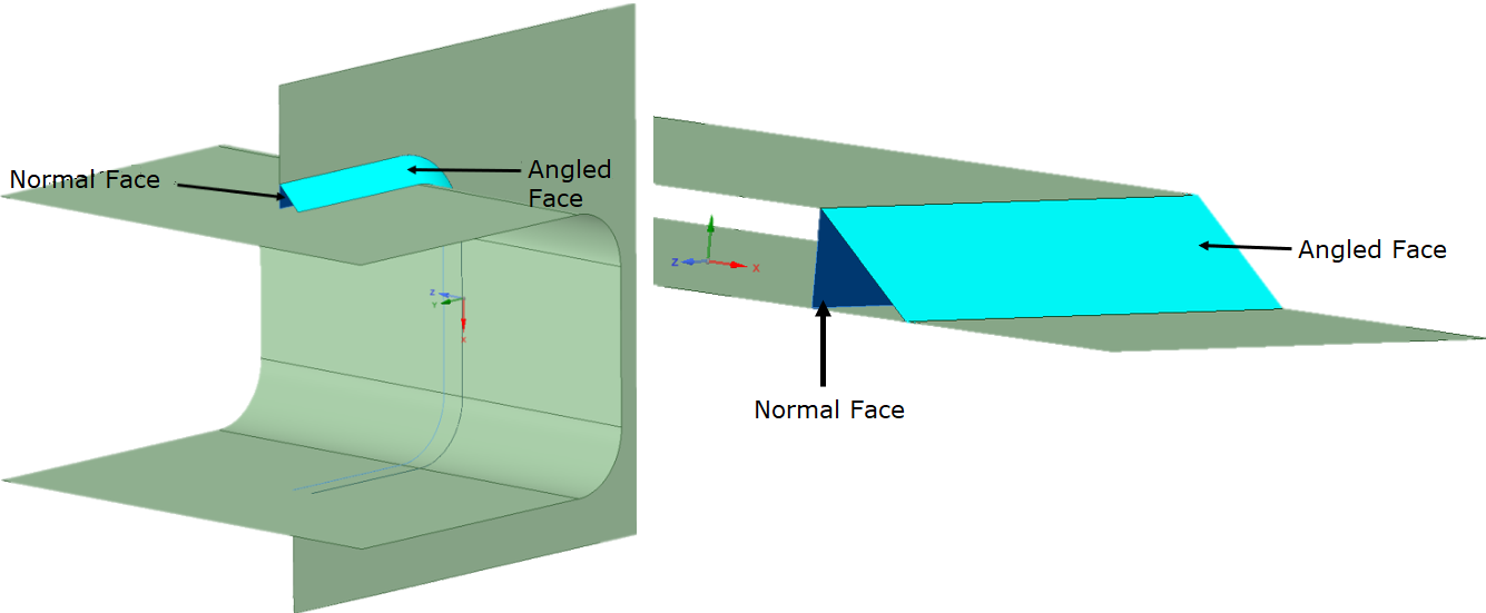
Angled: Creates mesh only on the angled face for the weld.
Normal: Creates mesh only on the normal face for the weld.
Normal and Angled: Creates mesh on the angled or normal faces with layers of quad mesh on both angled and normal with the user defined HAZ distance on top and bottom faces. When you select Normal and Angled, the Normal Surface and Angled Surfaces fields are available.
Parent Bodies Connection: Connects the top and bottom faces without creating quad layers on the angled or normal face. When you select Parent Bodies Connection, the Bottom Faces and Top Faces fields are available.
When you select the Source as Mesh, the available options are:
Normal and Angled: Creates both angled and normal face for the weld.
Angled: Creates only the angled face for the weld.
Normal: Creates only the normal face for the weld.
1D: Creates normal only weld using beams. Here beams are conformally connected to the top and bottom faces. For input edge or curves, the beams created are represented as a single body. 1D is available only when the Source is Mesh.
Note: 1D does not support Weld Element Rows.
Mesh Independent: Creates mesh without weld faces or HAZ layers. Mesh Independent is available only when the Source is Mesh. Nodes on the top faces are attached to the elements on the bottom face which act as contact points. To view the element faces attached to the nodes, click Show Mesh in the Display tab after generating mesh. Mesh Independent supports Solid-Solid weld creation.
Weld Element Rows: Allows you to split elements from weld faces. You can provide the number of splits required. The default value is 1. The value ranges from 1 to 2.
Create Using: Allows you to create weld using Curves, Curves and Bodies, Curves and Faces, Edges, Edges and Bodies or Edges and Faces. Available only when the Source is Mesh.
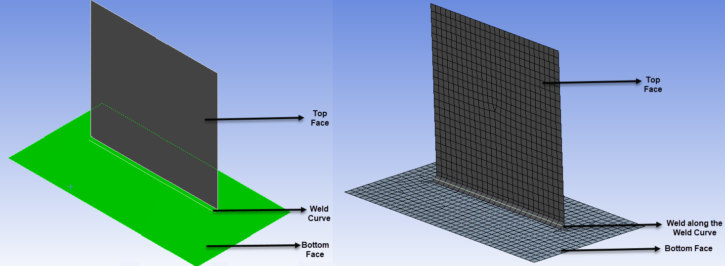
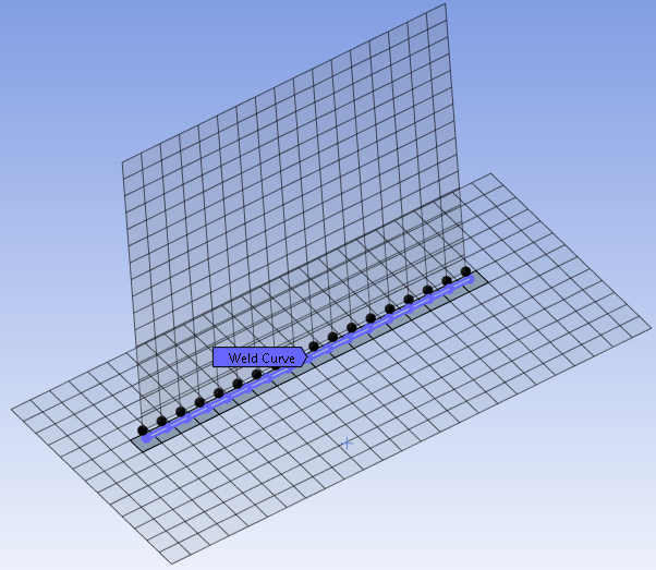
Curves: Allows you to pick a beam body and use it as weld curve. Software automatically determines the faces in proximity of the defined weld curve to be welded. When you select Curves, the Weld Curve option is available.
Curves and Bodies: Allows you to define bodies to be welded together in addition to the weld curve. When you select Curves and Bodies, the Bottom Bodies, Top Bodies, Weld Curve options are available.
Curves and Faces: Allows you to define faces to be welded together in addition to the weld curve. This option gives you better control on defining the scope for weld creation during mesh generation. When you select Curves and Faces, the Bottom Faces, Top Faces, Weld Curve options are available.
Edges: Allows you to scope geometry edges to create welds. The edges scoped to a weld control or in a row of worksheet must be continuous. When you select Edges, the Edges option is available.
Edges and Bodies: Allows you to define bodies to be welded together in addition to the geometry edges. When you select Edges and Bodies, the Bottom Bodies, Top Bodies, Edges options are available.
Edges and Faces: Allows you to define faces to be welded together in addition to the geometry edges. This option gives you better control on defining the scope for weld creation during mesh generation. When you select Edges and Faces, the Bottom Faces, Top Faces, Edges options are available.
Note: If the Curves or Edges option is providing incorrect result for weld creation, then using Curves and Faces or Edges and Faces is recommended.
Angled Direction: Allows you to specify the direction of the angle creation. The available options are Normal, Reversed and Both.
Normal: Allows you to create an angled face in the same direction of the face normal direct for edges-based inputs and along the weld curve for curve-based input.
Reversed: Allows you to create an angled face in the opposite direction of the face normal direct for edge-based input and opposite to the weld curve for curve-based input.
Both: Allows you to create an angled face along both the same direction and opposite direction of the face normal direct for edge-based inputs and both the same and opposite sides of the weld curve for curve-based input.
Use Worksheet: Allows you to use worksheet for weld controls. Worksheet enables you to combine multiple weld controls in a single weld control. The default value is No. For more details, see Weld Worksheet.
Curve Scoping: Available only when the Source is Mesh and Creating Using is set to either Curves, Curves and Bodies or Curves and Faces. The available options are Geometry Selection and Body Selection. The default value is Geometry Selection. Body Selection allows you to select the weld curve from the list of beam bodies.
Note: When you use beam bodies as weld curve, Treatment is automatically set to Construction Body. Treatment does not reset automatically, when the beam body is removed from the Weld Curve scope.
Definition
Suppressed: Suppress the weld control. The default value is No. When the value is set to Yes, the Active options appears with a read-only setting No,Suppressed.
Adjust Weld Height: Allows you to adjust the weld height. The default value is No. When the Adjust Weld Height is set to Yes, the Weld Height (Leg02) Assignment is available.
Weld Height (Leg02) Assignment: Allows you to select the weld height assignment. The available options for Weld Height (Leg02) Assignment are User Defined and Expression.
User Defined: Allows you to define the weld height. When you select User Defined, the Weld Height (Leg02) is available. Weld Height (Leg02) allows you to define the height of the weld created during mesh generation. The default value is calculated based on the average of the sheet thicknesses of the bodies connected by the weld. If the sheet thicknesses of the bodies are not available, no height adjustment is performed during mesh generation.
Expression: Allows you to calculate the weld height based on the expression. When you select Expression, the Weld Height (Leg02) Expression allows you to calculate the weld height based on the average thickness of the up and down faces. The Weld Height (Leg02) Expression should be based on t1 and t2, where t1 is the average thickness of all up faces and t2 is the average thickness of all down faces. Weld Height (Leg02) Expression allows only variables t1 and t2 as input and does not allow other variables.
Note: Variables t1 and t2 must be in lower case. Expression supports min, max and scientific numbering. Expression does not support any special characters other than the following mathematical operators like '+', '-', '/', '*', '^', '(', ')'. For Expression, you must specify constants in geometric unit and not in Workbench display units.
Weld Length: Allows you to define the length of each weld in the intermittent seam. The Weld Length is available only when the selected Type is Intermittent Seam. There is no default value for weld length. Thus, you must define the weld length manually.
Weld Pitch: Allows you to define the pitch of the weld. Weld Pitch is the distance from mid-point of one weld to the mid-point of adjacent weld in an intermittent seam weld. Weld Pitch is therefore the sum of the weld length and the gap between each of the welds. There is no default value for Weld Pitch. Therefore, you must define the Weld Pitch manually. Weld Pitch must be greater than Weld Length.
Number of Welds: Allows you to define the number of intermittent seam welds on the Weld Curve or Edge. You can also specify the number of intermittent seam welds. The intermittent seam welds are created based on the specified Weld Length and Weld Pitch. Once the defined Number of Welds is achieved, no further welds are created on the scoped Weld Curve or Edges.
Note: Weld Pitch and Number of Welds are optional. You can either provide Weld Pitch or Number of Welds value while performing weld operation.
Offset 1: Allows you to specify the distance between the start vertex and the first intermittent seam weld. The default value is 0.
Offset 2: Allows you to specify the distance between the last intermittent seam weld and the end vertex in the scoped Weld Curve or Edges. The default value is 0.
Creation Criteria: Allows you to define the criteria for the weld creation. The field is only available when the Source is Mesh. The default value is Width Based. The available options are:
Angle Based: Allows you to control the angle between the angled face and bottom face. When you select Angle Based for creating weld, the Weld Angle appears. The default value is 45 degrees. You can select any value from 30 to 60 degrees for Weld Angle.
Note: Normal face is always created perpendicular to the bottom face.
Width Based: Allows you to create welds of constant width along the weld line. When you select Width Based for creating weld, the available option is Weld Width (Leg01) Assignment. Weld Width (Leg01) Assignment allows you to select the type of weld width assignment. The available options are User Defined and Expression. The default value is User Defined.
User Defined: Allows you to provide the weld width. When you select User Defined, the Weld Width (Leg01) is set to Default. The Default value for Weld Width (Leg01) is equal to Weld Height (Leg02). If the Weld Height (Leg02) is not available, the Default is calculated as the default Angle Based.
Expression: Allows you to calculate the weld width based on the Weld Width (Leg01) Expression. When you select Expression, the Weld Width (Leg01) Expression calculates the weld width based on the expression. The expression should be based on t1 and t2, where t1 is the average thickness of all up faces and t2 is the average thickness of all down faces. Expression allows only variables t1 and t2 as input and does not allow other variables.
Note: Variables t1 and t2 must be in lower case. Expression supports min, max and scientific numbering. Expression does not support any special characters other than the following mathematical operators like '+', '-', '/', '*', '^', '(', ')'. For Expression, you must specify constants in geometric unit and not in Workbench display units.
Edge Mesh Size Assignment: Allows you to select the edge mesh size assignment. The available options are User Defined and Expression. The default is User Defined.
User Defined: Allows you to define the mesh size used to discretize the edges defined as weld lines. The default value for Edge Mesh Size is same as the global Element Size.
Expression: Allows you to calculate the edge mesh size based on the Edge Mesh Size Expression. Edge Mesh Size Expression calculates the edge mesh size based on the average thickness of the up and down faces. The expression must have only t1 and t2 as variables, where t1 is the average thickness of all up faces and t2 is the average thickness of all down faces.
Note: Variables t1 and t2 must be in lower case. Expression supports min, max and scientific numbering. Expression does not support any special characters other than the following mathematical operators '+', '-', '/', '*', '^''(', ')'. For Expression, you must specify constants in geometric unit and not in Workbench display units.
Note: The Edge Mesh Size should be reduced for welds involving high curvature.
Create HAZ Layer: Allows you to create the HAZ layer for the weld control when set to Yes. The default value is Yes. When Create HAZ Layer is set to Yes, the following options are available:
HAZ Distance Option: Allows you to define the HAZ Distance. The default value is the Global Element Size.The available options are Distance Per HAZ and Total Distance.
Distance Per HAZ: Allows you to specify the height for each quad layer.
Total Distance: Allows you to provide the total distance for which the HAZ layers are created. Here, Total Distance by Number of HAZ along with HAZ Growth Rate determines the height of each quad layer.
HAZ Distance Assignment: Allows you to select the type of HAZ distance assignment. When you set Create HAZ Layer to Yes , the HAZ Distance Assignment is available with User Defined option as default. The available options are User Defined and Expression.
User Defined: Allows you to provide the HAZ Distance. The HAZ Distance allows you to define the height for each quad layer. The default value is the Global Element Size. When you select User Defined, the HAZ Distance Top Plate allows you to specify the height of each quad layer for the top plate based on the selected HAZ Distance Option. HAZ Distance Bottom Plate allows you to specify the height of each quad layer for the bottom plate based on the selected HAZ Distance Option.HAZ Distance Top Plate and HAZ Distance Bottom Plate can be parameterized.
Expression: Allows you to calculate the HAZ distance based on the expression. The HAZ Distance Expression Top Plate allows you to calculate HAZ distance for top plate based on the expression. The HAZ Distance Expression Bottom Plate allows you to calculate HAZ distance for bottom plate based on the expression. The HAZ Distance Expression Top Plate and HAZ Distance Expression Bottom Plate should be based on t1 and t2, where t1 is the average thickness of all up faces and t2 is the average thickness of all down faces. HAZ Distance Expression Top Plate and HAZ Distance Expression Bottom Plate allow only variables t1 and t2 as input and do not allow other variables.
Note: Variables t1 and t2 must be in lower case. Expression supports min, max and scientific numbering. Expression does not support any special characters other than the following mathematical operators like '+', '-', '/', '*', '^', '(', ')'. For Expression, you must specify constants in geometric unit and not in Workbench display units.
Number Of HAZ: Allows you to define the number of quad layers generated from the weld lines. The default value for Number Of HAZ is 1 and the maximum number of layers that can be generated is 3. When Number Of HAZ is greater than one, Layer Transition Type allows you to specify the type of mesh elements to be created during the layer transition.
HAZ Growth Rate: Allows you to define the rate at which the HAZ layer grows. The default value is 1.2
Generate End-Caps: Allows you to generate triangular end-caps at the free ends of the welds. The default value is Yes.
Note:End-caps are not created when Modeled As is set to Normal.
End-caps are created when Modeled As is set to Angled. End-caps are usually created in plane of an angled face. However, if there is no enough space to create in-plane end-caps, then they can be created out of angled face plane.
Generate Named Selection: Creates FE named selection. The default value is No. The available options are:
Weld: Creates FE named selection on the weld body for the respective mesh control. This named selection is added under Named Selection tree-node with the name same as that of the weld control. The default value is No.
HAZ Layer 1: Creates named selection on mesh elements for the first offset layer.
HAZ Layer 2: Creates named selection on mesh elements for the second offset layer.
HAZ Layer 3: Creates named selection on mesh elements for the third offset layer.
Note: The HAZ Layer option created depends on the Number Of HAZ. That is, if the Number of HAZ is set to 1, only HAZ Layer 1 option is created. The HAZ Layer 2 and HAZ Layer 3 options are not created when the Number of HAZ is 1.
Note: You can parameterize Edge Mesh Size, Weld Height (Leg02), Weld Pitch, Weld Width (Leg01),Number of Welds, Offset 1, Offset 2, HAZ Distance, Layer Height, Weld Angle, Weld Length only when Use Worksheet is set to No. For more information, see Working with Meshing Application Parameters.
Mechanical Properties
Material: Allows you to define the material for the weld bodies created during meshing. You can only select the defined materials for weld bodies from the drop-down menu. The default option is None.
Cross Section: Allows you to assign cross section to weld bodies Modeled As 1D. This option is available only when Modeled As is set to 1D.
Thickness Assignment: Allows you to select different options to define the thickness of weld bodies created during meshing. The available options are:
Program Controlled: Allows the application to control the thickness of the weld bodies during meshing. The default value is Program Controlled. Here thickness is calculated as follows:
Weld Thickness = (Average thickness of top and bottom weld bodies) / √2
Min Parent Thickness Factor: Allows you to specify the minimum thickness factor for weld bodies during meshing. Here thickness is calculated as follows:
Weld Thickness= Min Parent Thickness Factor * min (Average thickness of all top and bottom faces for the created weld)
Max Parent Thickness Factor: Allows you to define the maximum thickness factor for weld bodies during meshing. Here thickness is calculated as follows:
Weld Thickness= Max Parent Thickness Factor * max (Average thickness of all top and bottom faces for the created weld).
Both: Allows you to specify the minimum and maximum thickness factor for weld bodies during meshing. Here thickness is calculated as follows:
Weld Thickness= Min Parent Thickness Factor * min(Average thickness of all top and bottom faces for the created weld) + Max Parent Thickness Factor * max(Average thickness of all top and bottom faces for the created weld).
User Defined: Allows you to define the Thickness value for weld bodies during meshing.
Expression: Allows you to calculate thickness of weld based on the expression. The weld thickness is calculated as the average thickness of all up and down faces. The expression should be based on t1 and t2, where t1 is the average thickness of all up faces and t2 is the average thickness of all down faces. Expression allows only variables t1 and t2 as input and does not allow other variables.
Note: Variables t1 and t2 must be in lower case. Expression supports min, max and scientific numbering. Expression does not support any special characters other than the following mathematical operators like '+', '-', '/', '*', '^', '(', ')'. For Expression, you must specify constants in geometric unit and not in Workbench display units.
Note: The Mechanical Properties options are not available when the Source is Geometry.
Advanced
Relaxation: Relaxes the HAZ layered failure. The available options are Conservative and None. The default value is Conservative.
Conservative : Provides warning for HAZ layered failures.
None: Provides error for HAZ layered failure.
Aggressive: Provides warning for weld face creation failures and HAZ layered failures. Aggressive option allows you treat failing welds as Mesh Independent irrespective of the setting or Type to handle weld face failures.
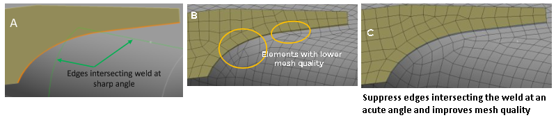
Sharp Angle: Allows you to automatically merge the bottom faces if the weld faces intersect them at an angle less than the specified value. The default value is 90 degrees. The Sharp Angle allows you to provide any value from 0 to 90 degrees.
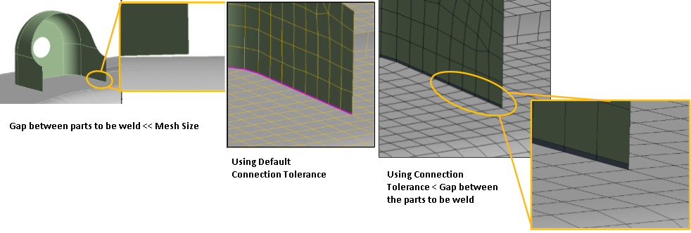
Connection Tolerance: Allows you to connect the weld bodies created during mesh generation to the parent metal bodies. Available only when the Source is Mesh. When two parts to be welded together are close to each other, the Connection Tolerance should be less than the gap between the parts to be weld.
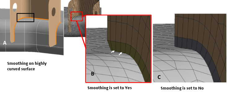
Smoothing: Available only when the Source is Mesh. The default value is Yes. Smoothing should be set to No for highly curved surfaces to achieve better results.
Butt Weld: Mark the weld elements and join them along their edges on the same plane when Butt Weld is Yes. Butt Weld is available only for Mesh Independent Weld.
Lap Weld Angle Tolerance: Allows you to adjust angled face direction by specifying appropriate angle. Lap Weld Angle Tolerance is available only when the Source is Mesh and Modeled As is either Angled or Normal and Angled. The default value is 5 degree. The acceptable range of Lap Weld Angle Tolerance is 0 to 90 degrees.
Pinball Radius: Allows you to calculate contact formulation while solving. Pinball Radius is available only when Modeled As is Mesh Independent. The default value is Element Size.
Layer Transition Type: Allows you to provide the mesh element type to be created during layer transition. Layer Transition Type is available only when the Number Of HAZ is greater than one. The default value is Quad. The available options are:
Quad: Allows you to create the quadrilateral mesh.
Quad/Tri: Allows you to create the mesh with both quadrilateral and triangular elements.
Quad/Minimal Tri: Allows you to create the mesh with more quadrilateral and less triangular elements.
Note: Quad/Minimal Tri pattern is used only in limited scenarios where good quality elements can be created.
Note: Cross hair is implemented for Edge Mesh Size, HAZ Distance and Connection Tolerance, the diameter of the cross hair is equal to the value of the corresponding parameter.
Weld Graphics Enhancements
Preview Weld Geometry: Allows you to preview the weld faces before meshing. It also allows you to view the errors and warnings for weld before meshing. You can access the Preview Weld Geometry from the Mesh object andWeld controls.
Preview Weld Mesh: Allows you to generate the weld mesh on the selected controls for preview. You can access Preview Weld Mesh from Mesh object and Weld control. Preview Weld Mesh creates mesh only for the weld faces and its corresponding up and down faces. You can also right-click any column in the Worksheet to access Preview Weld Mesh.
Color Coding
Weld helps you to visualize the status of the weld created based on the color of the weld control. The blue color weld control denotes successful weld creation. The yellow color denotes the warning and partial error in the weld creation. The red color denotes the failure in weld creation. The same color coding applies to the weld worksheet. When you select a weld control in a row in the worksheet, the selected weld control is highlighted in green color in the Geometry window and vice versa. The light blue color denotes the weld curve or weld in an unknown mesh state.
Show Mesh
Show Mesh displays the Weld and HAZ layer elements as solid and other elements as translucent. To access Show Mesh, in the Display tab click Show > Show Mesh.
Zoom to Weld
Zoom to Weld allows you to zoom to fit the scoped references of weld component. To access the Zoom to Weld, right-click the Geometry window and click Zoom to Weld. Zoom to Weld is automatically applied to the selected items in worksheet.
Seam Weld Review
Seam Weld Review allows you to hide the parts that are not scoped to weld. To access Seam Weld Review, in the Display tab click Show > Seam Weld Review.
Imported Data Highlight
Imported Data Highlight enables you to pick and highlight the weld components both in the geometry window and in the worksheet. You can access Imported Data Highlight from the Graphics toolbar.
Note: Weld supports Scripting. Scripting allows you to diagnose the weld errors and you can edit the Weld APIs to correct the same. For more detailed information on Weld Scripting, refer Accessing and Manipulating the Mesh Object and for more information on Weld Worksheet Scripting, refer Working with Weld Worksheet.
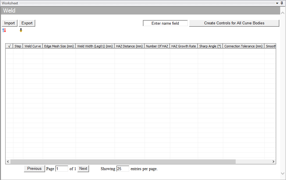
Weld Worksheet
Worksheet allows you to scope the weld controls. When Use Worksheet is set to Yes, Scope with Worksheet appears in the Details view which is a read-only field. The Worksheet opens and allows you to create weld controls. Worksheet provides different options based on the selected Source and Type. The options available in Worksheet are read only in the Details view. You can define these options in the Worksheet.
Note: Worksheet allows you to create weld controls for curved bodies using Body Selection.
Worksheet has the following features:
Import: Allows you to import the worksheet parameters as .CSV file format. You can also edit the CSV file if required. The .CSV file import format should be as given below:
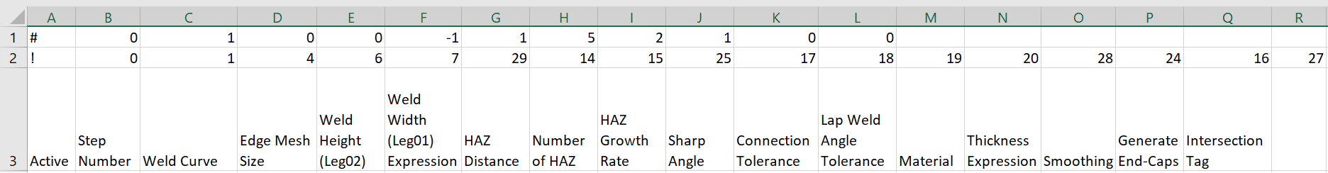
Rows 1 and 2 are used to populate the weld control Details view. The values in Row 1 and 2 should not be modified (Row 1 and Row 2 are for internal use only. Row 2 and Row 3 are not related. You must be using Row 3 onwards for working with worksheet). The values in Row 1 represents the following:
In Row 2, the numbers indicate the columns in worksheet. The details are as follows:
0 - Active
1 - StepNumber
2 - Bottom Face/Body/ Normal surface
3 - Top Face/Body/Angled surface
4 - Weld Curve
5 - Edge
6 - Edge Mesh Size
7 - Weld Height (Leg02)
8 - Weld Angle
9 - Weld Length
10 - Weld Pitch
11 - Number of Welds
12 - Offset1
13 - Offset2
14 - HAZ Distance
15 - Number of HAZ Layers
16 - Generate End-caps
17 - Sharp Angle
18 - Connection Tolerance
19 - Lap Weld Angle Tolerance
20 - Thickness Value
21 - Min Thickness Factor
22 - Max Thickness Factor
23 - Smoothing
24 - HAZ Growth Rate
25 - Cross Section Id
26 - Intersection Tag
27 - Thickness Expression
28 - Weld Width (Leg01) Expression
Note:Named selections for edges should be unique.
Named selection generated are always prefixed with weld_ in the name.
For each row, the edges scoped to the named selection must be continuous.
If welds are defined using Curves, then the names of weld curves must be unique.
Material is not available in Worksheet.
Export: Allows you to export the worksheet parameters as .CSV file format.
 : Allows you to sort all the
selected weld curves in the worksheet or the Geometry window in
ascending order and displays it on the first page of the worksheet.
: Allows you to sort all the
selected weld curves in the worksheet or the Geometry window in
ascending order and displays it on the first page of the worksheet. : Allows you to sort rows
based on its status.
: Allows you to sort rows
based on its status.Enter name field: Allows you search weld curves using the text entered in the textbox. When you enter the text in the Enter name field and click Create Controls for All Curve Bodies, worksheet displays all weld curves with the entered text.
Create Controls for All Curve Bodies: Allows you to create all weld curves. Also, records the operation and allows you to playback the same for reference.
Previous: Allows you to move to the previous page of the worksheet from the current page.
Next: Allows you to move to the next page of the worksheet from the current page.
Showing entries per page: Displays the number of allowed entries per page. This is an auto-populated entry.
Note: You can click the header of the worksheet columns to sort the items of the respective column.
Error Handling using Worksheet
Worksheet enables you to handle errors and failures efficiently. The
Worksheet rows highlighted in yellow indicates warning messages. The red
highlighted rows indicate error messages. The grey highlighted rows indicate the invalid weld
or suppressed geometry. The  allows you
to send the weld for meshing. White is for active and valid weld with valid geometry. Only
active rows can be provided as input for meshing. When your input to worksheet has a
suppressed body, the weld worksheet row is highlighted in grey but will be active.
allows you
to send the weld for meshing. White is for active and valid weld with valid geometry. Only
active rows can be provided as input for meshing. When your input to worksheet has a
suppressed body, the weld worksheet row is highlighted in grey but will be active.
When you set the Use Worksheet to Yes and right-click the Weld object in the tree view, the following options are available:
Deactivate Problematic Worksheet Entries: Allows you to deactivate the row which is causing error while meshing.
Right-click the Worksheet, the following options are available:
Add: Allows you to add a row to the worksheet.
Delete: Allows you to remove a row in the worksheet.
Activate all Selections: Allows you to activate the multiple rows selected.
Deactivate all Selections: Allows you to deactivate the multiple rows selected.
Go To Selected Items in Tree: Allows you to go to the selected worksheet item in the tree.
Promote to Weld Control: Allows you to create new weld control for the selected worksheet row. These rows are added to a new worksheet created for the new weld control.
Paste From Clipboard: Allows you to copy the text from clipboard to worksheet.
Preview Weld Mesh: Allows you to generate the weld mesh on the selected controls for preview from the worksheet.
Preview Weld Geometry: Allows you to preview the weld faces before meshing from the worksheet. It also allows you to view the errors and warnings for weld before meshing.
Note: Weld Worksheet allows you to select the faces, edges and bodies only through named selections and you cannot add faces, edges and bodies to the weld worksheet selection from the Geometry window.
Weld Limitations
The Weld control has the following limitations:
Weld control does not support Connect and Mesh Selected Entities option.
Combined length of all angled faces and combined length of all normal faces should be same.
Weld control overrides all other sizing and local control settings.
The selection option for Weld Curve does not support multiple bodies.
CAD edges scoped in a weld control or in one row of weld control worksheet must be continuous.
Weld control does not support intersecting welds for all sources.
Weld Control does not support triangular mesh, when you select Mesh Type as Triangles.
Weld Worksheet allows you to import only files with plain CSV format.
The Weld control does not support writing Weld Definition File for multiple edges or closed loop selections.
Solid Shell welds could fail for solver if Solid-Shell Weld – Shared Nodes is Yes under Meshing in Files > Options > Meshing.