


This section provides basic information on how to get BladeGen running on a computer.
Please refer to the installation instructions in the ANSYS Help documentation.
To launch BladeGen from Ansys Workbench, add the BladeGen component system to your Project Schematic pane, then edit the Blade Design cell of that system. BladeGen can be started in other ways; for details, see Starting BladeGen in Ansys Workbench .
The Blade Design cell has properties that must be configured in order to transfer the blade geometry from the BladeGen component system to another system. Such a transfer is carried out by right-clicking the Blade Design cell and selecting one of the context menu commands under the Transfer Data To New sub-menu. The transfer is represented in the Project Schematic pane by a link that connects the Blade Design cell to a downstream cell in another system.
To see the cell properties of the Blade Design cell, select that cell. If necessary, turn on the Properties pane from the View menu. Most of the cell properties are described in Table 9.2: BladeGen Blade Design Cell Properties.
Table 9.2: BladeGen Blade Design Cell Properties
|
Group |
Name |
Description |
|---|---|---|
|
Data Transfer |
Geometry Transfer Type |
This property specifies the file format used to transfer geometry from the Blade Design cell to another system. If Import BGD is selected, then the BGD format is used. If Load NDF is selected, then the NDF (*.ndf;*.xml) format is used. Note that you cannot change this property while there is a connected downstream cell. The default value of this property is set by a Workbench preference: Tools > Options > TurboSystem > Blade Design > Data transfer type. |
|
Import Options (available only if Geometry Transfer Type is set to These properties are related to the properties of the ImportBGD feature in BladeEditor (described at Table 10.4: Properties for the ImportBGD Feature). |
Create Hub* |
If this property is selected, then BladeEditor will
create a |
|
Create All Blades |
If this property is selected, then BladeEditor will create all the blades using the number of blades specified in the BladeGen model. If this property is not selected, then only the first blade will be created. | |
|
Merge Blade Topology |
If this property is not selected, then BladeEditor will create the blade with four faces corresponding to the leading edge, pressure side, trailing edge and suction side. This can make it easier to create a structural mesh for the blades in the Mechanical application. If this property is selected, then the blade faces will be merged where they are tangent to one another. | |
|
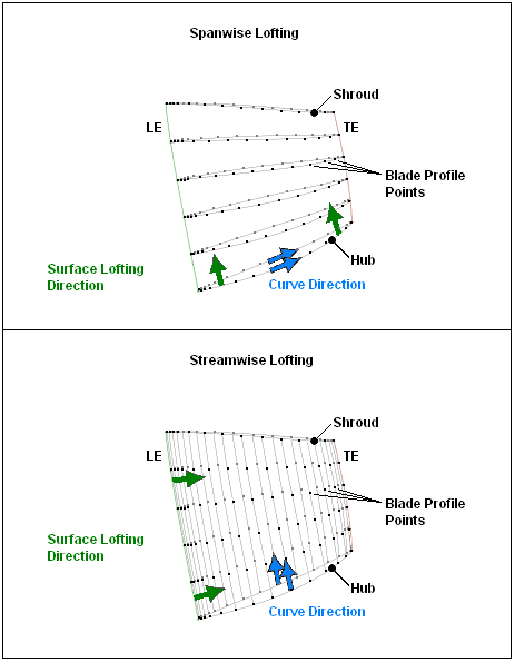
If this property is set to If this property is set to For an illustration of these lofting methods, see the figure after this table. | ||
|
This property specifies whether
a shroud clearance is created. If If If | ||
|
Create Fluid Zone* |
If this
property is selected, then BladeEditor will create a | |
|
If this property is selected,
then BladeEditor will create Note that this property is available only if Create Fluid Zone is selected. | ||
|
Blade Extension (%) |
This property defines the surface extension
length (as a percentage of the average hub to shroud distance) for
the blade surfaces. These surfaces are extended and then trimmed to
the | |
|
Periodic Surface Extension (%) |
This property defines the surface extension length (as
a percentage of the average hub to shroud distance) for the periodic
surfaces. These surfaces are extended to ensure that the | |
|
Periodic Surface Style |
This property specifies the style of the periodic interface surfaces. If If Note that this property is available only if Create Fluid Zone is selected. | |
|
Vista TF Export |
Streamwise mesh count |
[Integer Value > 2] |
|
Spanwise mesh count |
[Integer Value > 1] |
* These properties will apply only when you initially transfer the model. Any subsequent changes to these properties will not propagate downstream to the cells of other systems.
Figure 9.5: Spanwise Lofting versus Streamwise Lofting shows how spanwise lofting and streamwise lofting differ.
Once the ImportBGD feature has been created (for example, by updating the Geometry cell), changing the following Blade Design cell properties will have no effect:
Create Hub
Create Fluid Zone
Create Named Selections
Note: In order to facilitate the use of a BladeGen model in
another application (such as BladeEditor or Ansys TurboGrid), you should always
ensure that the model units are set. When you create a new BladeGen model
(File > New > BladeGen Model), the default units are always "Unknown" (regardless of Ansys Workbench preferences). In
this case, select Model > Properties from the BladeGen main menu and set
Model Units in the Model
Property Dialog.
You can access a context menu for the Blade Design cell in the BladeGen component system by right-clicking the cell. Most of the commands that are available are standard, and are described in Cells in Workbench. The context menu commands that are specific to the Blade Design cell are described in Table 9.3: Context Menu Commands Specific to the BladeGen Blade Design Cell.
Table 9.3: Context Menu Commands Specific to the BladeGen Blade Design Cell
|
Command |
Description |
|---|---|
|
Create New Blade CFD Mesh |
This command creates a linked[a] Mesh system and generates a mesh for the associated BladeGen model. This command is available only if the cell is up to date and the geometry has been saved (either by saving it from within BladeGen or by closing the BladeGen window). Also see Tips on Using the Create New Blade CFD Mesh Command. |
|
Edit |
This command opens BladeGen. If the cell is up to date, then BladeGen will load the associated BladeGen model. |
|
Import Existing Case |
This command opens a file browser for selecting a BladeGen File (*.bgd) or Neutral Data File (*.ndf). This command is only available if the cell is in the Edit Required state. If this command is not available due to having already selected a file, and you want to make the command available so that you can select a different file, then choose the Reset command in the context menu. |
|
Transfer Data to New > Fluid Flow (CFX) |
This command creates a Fluid Flow (CFX) system and links it to the BladeGen system. |
|
Transfer Data to New > Geometry |
This command creates a Geometry system and links it to the BladeGen system. |
|
Transfer Data to New > Mesh |
This command creates a Mesh system and links it to the BladeGen system. |
|
Transfer Data to New > Throughflow |
This command is not recommended. Instead, use the Transfer Data to New > Vista TF command. |
|
Transfer Data to New > TurboGrid |
This command creates a TurboGrid system and links it to the BladeGen system. |
|
Transfer Data to New > Vista TF |
This command creates a Vista TF system and links it to the BladeGen system. Geometry transfer from a BladeGen system to a Vista TF system is restricted to ruled element blades, that is, those defined by hub and shroud profiles only. |
|
Create New > Geometry |
This command creates a Geometry system based on the BladeGen system. This command launches Ansys DesignModeler (with BladeEditor) and generates the new model using a Load BGD operation (see Loading and Modifying Blades from Ansys BladeGen). The DesignModeler model is detached from the BladeGen system (that is, no link is generated). Therefore, any changes made to the BladeGen system will not be reflected in the DesignModeler model following an update of the BladeGen system. When you use this command, you will receive a warning or error message for any feature of the BladeGen case that cannot be reflected in the DesignModeler model. A list of such features is given in Limitations of Loading BladeGen cases into BladeEditor. |
[a] Note that the link between systems causes the geometry to be
imported, rather than loaded, into BladeEditor. The blade will be dependent
on the BladeGen BGD file, but you can still modify the HubProfile sketch that appears under the associated MerPlane feature. For more information on importing
and loading geometry into BladeEditor, see Transferring Blades from Ansys BladeGen in the TurboSystem User's Guide and Loading and Modifying Blades from Ansys BladeGen in the TurboSystem User's Guide.
To start BladeGen, perform one of the following. Note that certain options are not available until a license key is obtained.
From the Start menu, start Ansys Workbench, then add a BladeGen component system to the Project Schematic (double-click the BladeGen component system in the Toolbox, or drag the BladeGen component system from the Toolbox to the Project Schematic), then edit the Blade Design cell of the new BladeGen system.
Open a *.bgd file from Windows Explorer (including the Windows desktop) by double-clicking the file. A new instance of Workbench will open, with a BladeGen system that has a copy of the *.bgd file associated with it. Edit the Blade Design cell to open BladeGen.
You can drag and drop a *.bgd file into the Project Schematic. This will create a new BladeGen system that has a copy of the *.bgd file associated with it. Edit the Blade Design cell to open BladeGen.
You can drag and drop a *.bgd file into an open BladeGen window to load a copy of the file into BladeGen. If BladeGen previously had no blade design, then the one you dragged in becomes associated with the cell of the BladeGen system.
Visual Expansion is on by default. This displays a full 360° mesh in Ansys Meshing for visualization purposes. To display only the actual single passage mesh, clear Visual Expansion in the View menu of Ansys Meshing.
If the mesh fails to be generated, try the following procedure to adjust the fineness of the mesh:
Edit the Mesh cell of the Mesh system.
The Ansys Meshing window appears.
In the tree view, select Mesh.
In the details view, adjust the settings for the Sizing controls directly, for finer control.
If the geometry has a small radius on the leading edge or trailing edge, the resulting mesh might be finer than wanted. In this case, you can try increasing the minimum element size manually by, say, a factor of 4. For details on the Curvature Min Size control, see Curvature Min Size in the Meshing User's Guide.
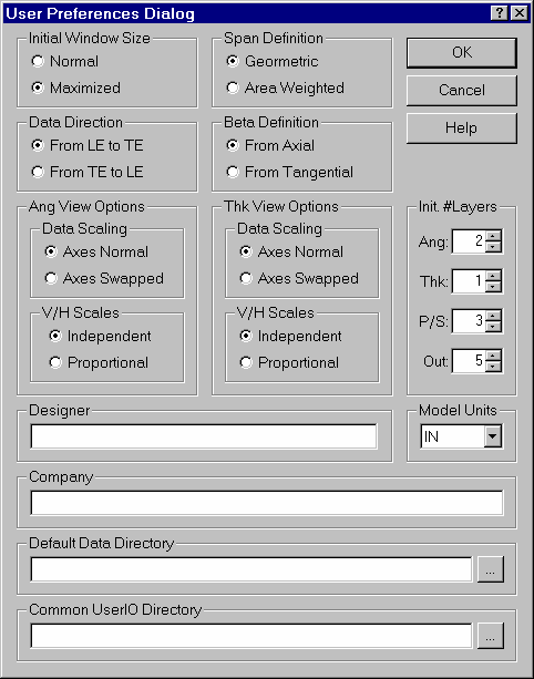
BladeGen allows the user to customize the modeling environment by setting up default preferences. This is done with the User Preferences Dialog shown below. This dialog can be displayed using the File | Preferences... menu command. It allows the user to set up parameters such as window size, data definitions, viewing options, initial layer definitions and default data directories.
These settings are saved between sessions, allowing users to initiate BladeGen with their preferred environment and create new models using the specified settings. Existing models store the settings internally, and will be unaffected by changes to the user preferences.
The following topics are discussed:
A new blade can be created in a number of ways. The easiest is to start from scratch. Importing a file from a preliminary design program is also simple. It is a little more difficult to import meanline data, if the import tool has to be created first. The most difficult to import CAD data, because it has to be converted to meanline data to be used in BladeGen.
The following topics are discussed:
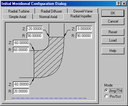
BladeGen allows the user to create a blade system from scratch, using one of six standard initial configuration types. The following section describes this process.
Select the File | New | BladeGen Model menu command or
 toolbar button, which will display the Initial Meridional Configuration Dialog (shown below).
Select the tab with the configuration closest to the desired component.
Enter the parameters for the given configuration type.
Press Enter or select the OK button to display the dialog box below.
Related Topics
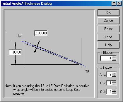
If a radial component was selected in the Initial Meridional Configuration Dialog, the Initial Angle/Thickness Dialog, shown below, will be displayed and the model will be created using the Angle/Thickness mode. To complete the process:
Enter the nominal wrap angle, thickness and number of blades using the dialog’s input fields. Normally, BladeGen sets the leading edge theta to zero. If the Data Direction is set to TE to LE in the User Preferences Dialog, then the trailing edge theta is set to zero.
Press Enter or select the OK button to display the BladeGen Window.
Related Topics
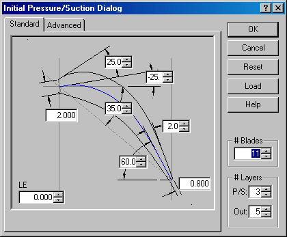
If an axial component was selected in the Initial Meridional Configuration Dialog, the Initial Pressure/Suction Dialog, shown below, will be displayed and the model will be created using the Pressure/Suction Mode. To complete the process:
Enter the required parameters using the input fields of the Standard tab. These parameters control the shape of the Bezier curves that define the blade.
Select the Advanced tab to enter the advanced parameters, if desired. These parameters control the distances between points on the Bezier curve and the length of an optional linear segment.
Enter the initial number of blades and layers.
Press Enter or select the OK button to display the BladeGen Window.
Related Topics
BladeGen provides various methods to import geometry. See Data Import/Export for further details.
Some preliminary design codes export a BladeGen file (BGI) which allows the geometry to be imported. This makes the import seamless. See Batch Input File for further details.
If the data is meanline data (r,t,z,Tn), it can be read (and written) using a User Input/Output (UserIO) routine. A few UserIO routines for various file formats are shipped with BladeGen. Users are encouraged to use these as examples and tailor the source code to fit their needs. See UserIO (User-Defined Meanline Data Import/Export) for further details.
The most difficult type of data to import is the generic CAD data, which describes the hub, shroud, and blade surface (as a surface or a curve set). This type of data can be imported using the Data Import Wizard. The following file types are supported: TurboGrid File Sets (*.curve), IGES 5.3 File (*.iges or *.igs), PRO/ENGINEER ‘ibl’ File (*.ibl), or General Data File (*.dat). See Data Import Wizard for further details.
The following topics are discussed:
Native BladeGen Data files are saved with a ’.bgd’ file extension and a Batch Input File is saved with a ’bgi’ file extension. Additionally, files supported by UserIO routines are opened as native files. All of these files can be opened in the following ways:
Using the File | Open... menu command or the
 toolbar button to open a data file. A browse window will appear, allowing the user to select a file. Examples of several blade configurations can be found in the "Example" directory (See the section titled Opening an Example File for more detail.)
Dragging a file from Windows Explorer, and dropping it onto BladeGen’s main window or an icon on the Desktop.
Double-clicking on a file in the Windows Explorer.
Related Topics:
The BladeGen installation includes a number of example files that can be used to provide insight into some of BladeGen’s modeling techniques. Some of these files, which are included in the "Examples" sub-directory, are shown below.
These files can be opened in one of two ways:
Using the File | Open... menu command or the
toolbar button and then navigating to the "C:\Program Files\ANSYS Inc\v###\AISOL\BladeModeler\BladeGen\Examples" subdirectory (or similarly named subdirectory, where ### is a version number such as "130").
Using Windows Explorer, browse to the example directory and double-click the desired file.
The examples that are available may differ from those shown below.
Upon exiting BladeGen, the blade model is automatically saved to a file associated with the Workbench project. You must save the project before closing it in order to retain the project files. You can save the project from the Workbench interface as usual. You will be prompted for a project name if you have not previously saved the project. The File | Save menu command (Save ![]() toolbar button) can function as an alternative way to save the project, depending on a condition described shortly.
toolbar button) can function as an alternative way to save the project, depending on a condition described shortly.
The first blade model to exist in BladeGen, whether by opening a bgd file or by creating a blade from scratch, becomes associated with the Blade Design cell from which that instance of BladeGen was started. Any other blade models that are subsequently opened in the same instance of BladeGen (in separate "windows", selectable from the Window menu) are not associated with the cell (or even the project).
When the active window in BladeGen is the one containing the model associated with the Blade Design cell:
The File | Save menu command (Save
 toolbar button) in BladeGen saves the (entire) Workbench project. As in Workbench, you will be prompted for a project name if you have not previously saved the project. This command is unavailable if there are no unsaved changes in the model in the active window in BladeGen, even if there is an unsaved change elsewhere in the project.
The File | Save As… menu command (Save As
 toolbar button) is unavailable.
When the active window in BladeGen is not the one containing the model associated with the Blade Design cell:
The File | Save menu command (Save
toolbar button) acts to save only the .bgd file for the model in the active window.
The File | Save As… menu command (Save As
toolbar button) acts to save only the .bgd file for the model in the active window, and prompts you for the new file name and location.
When operating in Demo Mode (without a license), you are prevented from either saving or exporting data. If the software had a valid floating license and lost it because of a network or other failure, BladeGen notifies you that the license has been lost. In this condition, BladeGen allows you to save your data only once.