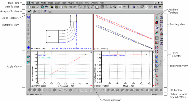
A typical BladeGen Window contains a combination of Working Views and Auxiliary Views. The Working Views are views where all blade-modification tasks are performed. The Auxiliary Views are used for data display only and provide a variety of formats for reviewing the blade design. The operating mode determines which working views are active. The Annotated Window Layout, show below, describes the components of the window.
Each view has a unique set of functions and operations that can be accessed using context-sensitive popup menus. These menus are displayed by positioning the cursor in the relevant view and depressing the right mouse button. Some of the functions in these popup menus are accessible from the main menu, but many are unique to the popup menus. See Menu List for a complete listing of menus.
The following topics are discussed:
BladeGen uses a common set of mouse functions to manipulate the views. These functions are described in the following table.
Table 9.4: Common Mouse Functions
|
Mouse Action |
Applies To |
Description |
|---|---|---|
|
Click with Left |
Working Views only |
If a point or segment is within selection distance, it is selected. |
|
Drag with Left |
Working Views only |
If a point is selected or within selection distance, the point is selected and dragged with the mouse pointer. Releasing the mouse button updates the view. |
|
Scroll wheel or Drag with Both |
All Views |
Zooms the view in and out |
|
Click with Right |
All Views |
Displays the context-sensitive popup menu. |
|
Drag with Right |
All Views |
Pans the view. The view moves with the mouse pointer. |
Between each of the views in the BladeGen Window are view separators, as shown in Figure 9.10: Annotated BladeGen Window Layout (Angle/Thickness Mode). These view separators can be dragged to resize windows by positioning the mouse over a separator, pressing the left button, and dragging to the new location. Pressing the toolbar buttons shown below can also control the layout of the views. By utilizing these methods, the user can control the amount of space consumed by each view and can tailor the display to match the current task.
![]() Maximize the Top Left (Meridional) View
Maximize the Top Left (Meridional) View
![]() Maximize the Bottom Left (Angle or Prs/Sct) View
Maximize the Bottom Left (Angle or Prs/Sct) View
![]() Maximize the Bottom Right (Thickness or Prs/Sct) View
Maximize the Bottom Right (Thickness or Prs/Sct) View
![]() Maximize the Top Right (Auxiliary) View
Maximize the Top Right (Auxiliary) View
![]() Restore View Layout, with all views the same size
Restore View Layout, with all views the same size
The Meridional and Auxiliary views are common to both the Angle/Thickness and Pressure/Suction Modes. These views appear on the top half of the BladeGen window, as shown below, and are described in more detail in the following sections:
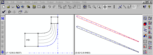
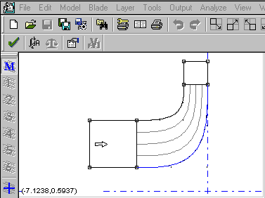
A typical Meridional View is shown below. The meridional view contains the description of the blade in an axial-radial coordinate system. BladeGen allows the user to define the blade and the inlet/outlet extensions required by CFD programs. See Meridional View Popup Menu for details of the options and functions available in this view.
The following commands are available:
Point Drag Control Submenu - See Point Drag Control Submenu.
Convert Points to Submenu - See Convert Points to Submenu.
Segment Type Submenu - See Segment Type Submenu.
Move Curve Submenu - See Move Curve Submenu.
Use Hyperbolic Shape Submenu - See Use Hyperbolic Shape Submenu.
Meridional Profile Submenu - See Meridional Profile Submenu.
Meridional Control Curves Submenu - See Meridional Control Curves Submenu.
Display Interpolation Grid - Toggle the display of the Meridional Interpolation Grid on/off. The Display Interpolation Grid command toggles the display of the S/T Interpolation Grid on/off (in the Meridional View).
Display Blade Centroid Curve - Toggle the display of the centroid curve for the current blade on/off. The Display Blade Centroid Curve command toggles the display of the blade centroid curve on/off (in the Meridional View).
Display Throat Mid-Point Curve - Toggle the display of the throat line midpoints for the current blade on/off. The Display Throat Mid-Point Curve command toggles the display of the throat line midpoints on/off (in the Meridional View).
Display Orthogonal Curves - Toggle the display of the Quasi-Orthogonal Curves on/off. The Display Orthogonal Curves command toggles the display of Orthogonal Curves on/off (in the Meridional View).
Display Equal Distance Curve - Toggle the display of the Equal Distance Curve (centerline path of maximum possible diameter circle) on/off. The Display Equal Distance Curve command toggles the display of the Equal Distance Curve (centerline path of maximum possible diameter circle) on/off.
Copy View Image/Data to Clipboard - Copy the Current View’s Image and/or Data to the Clipboard (in text, bitmap, or metafile formats). This allows transfer of data to reports, spreadsheets, and presentations for documentation of the blade design.
Zoom Fit - See Zoom Fit.
Any Direction - Drag in any direction (default). The Any Direction command allows points to move in any direction during curve editing. This is the default option.
Horizontal Only - Drag only in the horizontal direction. The Horizontal Only command constrains points to move in the horizontal direction only during curve editing.
Vertical Only - Drag only in the vertical direction. The Vertical Only command constrains points to move in the vertical direction only during curve editing.
Spline Curve Points... - Create a point set with the specified number of points for a Spline Curve. The Spline Curve Points... command converts the selected curve segment to the ’Best Fit’ Bezier with the specified number of points.
Bezier Control Points... - Create a control point set with the specified number of points for a Bezier Curve. The Bezier Control Points... command converts the selected curve segment to a spline with the specified number of points, without changing the shape of the curve. This new curve can subsequently be changed to Linear or Best Fit Polynomial.
Piecewise Linear Segment - Use the current points for a Piecewise Linear Curve. The Piecewise Linear Segment command changes the representation of the curve’s or segment’s data to Piecewise Linear. This curve type produces a curve that uses lines between the points used to define it. This operation does not change the location of the points.
Cubic Spline Segment - Use the current points for a Cubic Spline Curve. The Cubic Spline Segment command changes the representation of the selected segments data to a Lagrangian Spline. This curve type produces a curve that intersects the points used to define it. This operation does not change the location of the points.
Bezier Segment - Use the current points as control points for a Bezier Curve. The Bezier Segment command changes the representation of the selected curve’s or segment’s data to a Bezier Curve. This curve type produces a curve that intersects the points used to define it.
Best Fit Polynomial Segment - Use the current points for a Fitted Polynomial Curve. The Best Fit Polynomial Segment command changes the representation of the selected curve’s or segment’s data to a Best Fit Polynomial. This curve type produces a curve defined by a polynomial of the selected order where the coefficients of the polynomial are selected to best fit the data. This operation does not change the location of the points.
Arc Segment - Change segment to an Arc Segment. The Arc Segment command changes the currently selected segment to an Arc Segment.
Intersect Two Points - Move curve to intersect two points. The Intersect Two Points command prompts the user for two points through which the curve should pass. When the user presses OK, the best (z,r) offset is calculated. The user is then prompted to confirm the (z,r) offset before the offset is applied.
by Offset - Move curve by offset (z,r). The by Offset command prompts the user for the (z,r) offset for the selected curve. When the user presses OK, the curve is move by the specified offset.
Never - Spanwise curves should always retain their meridional shape. The Never command specifies that the hyperbolic shape created when the blade angles at the hub and shroud differ should be ignored. The meridional shape of the blade will then be exactly the shape of the meridional curve.
Ruled Element Only - Spanwise curves assume a hyperbolic shape when angle distribution is ruled element. The Ruled Element Only command specifies that the hyperbolic shape created when the blade angles at the hub and shroud differ should only be used when the Angle Definition is Ruled Element and only two points are used to define the specific Meridional Cutting Curve.
Any Blade Type - Spanwise curves assume a hyperbolic shape for any blade type. The Any Blade Type command specifies that the hyperbolic shape created when the blade angles at the hub and shroud differ should only be used whenever only two points are used to define the specific Meridional Cutting Curve.
Force Hyperbolic Shape - Force a Hyperbolic Shape on all spanwise curves by deleting interior points and segments, as required. The Force Hyperbolic Shape command forces the Meridional Cutting Curves (LE/TE and LE/TE Cuts) to be defined by two points, enabling the ruled element shape to be used.
Show Design Profile - Display the Design Profile for modification. The Show Design Profile command selects the Design Definition for display in the Meridional View.
Show Trim Profile - Display the Trim Profile for modification. The Show Trim Profile command selects the Trim Definition for display in the Meridional View.
Show Other Profile - Show the non-active definition. The Show Other Profile command toggles the display of the non-active Meridional Definition on/off.
Create Trim Profile - Create a separate Trim Profile from the current Design Profile. The Create Trim Profile command creates a separate Trim Definition from the current Design Definition.
Recreate Trim Profile - Recreate the Trim Profile from the current Design Profile. The Recreate Trim Profile command recreates the trim definition from the Design Meridional Definition. It is equivalent to deleting the Trim Definition and then creating it from scratch.
Delete Trim Profile - Delete the Trim Profile and use only the Design Profile. The Delete Trim Profile command deletes the Trim Definition and selects the Design Definition.
Minimal - Disables the use of control curves at 35% and 65% of the meridional length. The Minimal command forces the use of only the LE and TE curves as Meridional Control Curves.
Normal - Enables the use of control curves at 35% and 65% of the meridional length. The Normal command forces the use of the LE and TE curves and 35% and 65% curves as the Meridional Control Curves.
User-Defined - Enables user definition of all control curves. The User-Defined command switches to User-Defined Meridional Control Curves. In this mode, the user can insert, modify, and delete Meridional Control Curves to correct for difficult geometry.
Insert - Insert a Meridional Control Curve at the next left mouse click location. The Insert command activates the ability to insert a single control curve at the next location the left mouse button is clicked. The curve is positioned by determining the closest points of the hub and shroud. It is best to click in the flow passage between the hub and shroud for this operation.
Delete - Delete the currently selected Meridional Control Curve. The Delete command deletes the currently selected Meridional Control Curve.
Suggest - Suggest a rough location for a Meridional Control Curve. The Suggest command determines if a new Meridional Control Curve is needed based upon the angle of the grid lines to the hub and shroud curve normals. If the maximum angle exceeds 30°, then a single curve is inserted at this location. The user should reposition the control curve to provide the best grid control possible.
Modify - List user-defined control curves by end location and allow insertion and deletion.
The Auxiliary View is located in the upper-right corner of the BladeGen window, as shown in the figure below. It is used to display various data sets describing the model. The Auxiliary View is automatically updated when modifications are performed in a Working View.
The data set to be displayed is selected by the View | Auxiliary View Content menu commands and the Auxiliary Toolbars (displayed by default on the right edge of the window). The user may create additional auxiliary views by invoking the New Auxiliary View (B2B) menu command, either from the View menu or from the popup menu in an Auxiliary View. This will create a new Blade-to-Blade view which can then be changed to the desired type by using the Auxiliary View Content menu command.
There are currently five Auxiliary View types. They are described in Auxiliary View Details . See the View Submenu (View Submenu) or the popup menu for the view type for details of the options and functions available in this view.
The Angle/Thickness Mode Specific Views are used to define the angular location and thickness of a blade, as a function of some location on the layer curve. This data indirectly specifies the location of the two sides of a blade. Both views use a quantity derived from the meridional distance along a layer as the independent axis.
The following sections describe these views in more detail:
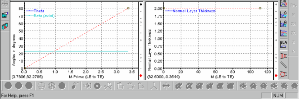
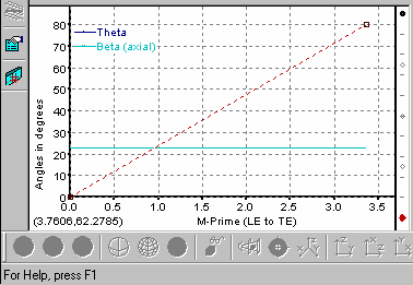
The Angle View, shown below, describes the angular placement (Theta or  ) and slope (Beta or
  ) of the blade on a layer. See Angle View Popup Menu for details of the options and functions available in this view.
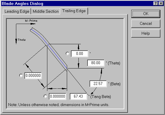
The user can modify the data of the curve directly or use the Blade Angles Dialog (Blade Angles Dialog) to specify common values which will be used to create a curve that satisfies the parameters.
Adjust Blade Angles... - Recreate the angle layer from the parameters in the Blade Angle Dialog.
Point Drag Control Submenu - See Point Drag Control Submenu.
Convert Points to Submenu - See Convert Points to Submenu.
Segment Type Submenu - See Segment Type Submenu.
Segment Operations Submenu - See Segment Operations Submenu.
End Angle with Beta Slope=0 Definition - Define the theta curve by the end points of the theta and beta curves as a polynomial, with second derivative set to zero at the end points.
End Angle Definition - Define the theta curve by the end points of the theta and beta curves as a polynomial.
Theta Definition - Define the theta curve directly.
Beta Definition - Define theta by beta and the initial theta value. The Beta Definition command defines the theta curve by a beta curve and the initial theta value. The existing beta curve is used to generate the points used to define the new beta curve. The number of points used is specified by the user.
Theta @ Beginning... - Specify the leading edge (no cut-off) Theta value. The Theta @ Beginning... command displays a dialog to allow the user to specify the leading edge (no cut-off) Theta value for the Beta definition of the blade.
vs. M-Prime - Set the horizontal axis dimension to radius normalized meridional distance (M’).
vs. % M-Prime - Set the horizontal axis dimension to the percent of the total radius normalized meridional distance (%M’).
vs. M - Set the horizontal axis dimension to meridional distance (M).
vs. % M - Set the horizontal axis dimension to the percent of the total meridional distance (%M).
Show Second Angle Curve - Toggle the display of the derived curve (theta or beta) on/off.
Show Curve for each Defining Layers - Toggle the display of the angle curves for all defining layers (other than the current layer) in the background, in gray.
Show Legend - Toggle the display of the legend on/off.
Swap Axes - Swap the horizontal and vertical axes of the selected graph.
Proportional Axes - Toggle the proportionality setting of the graph axes on/off.
Layer Control... - Display the Layer Control Dialog for the current Angle Definition. The user can create layers and/or check or uncheck the check box to signify which layers will be used for the Angle Definition. When both new layers are added and current layers are removed, the checked layers are added before the unchecked layers are removed.
Layer Submenu - The Above command changes the displayed layer to the next layer above (by span). The Below command changes the displayed layer to the next layer below (by span). These commands allow rapid changes in the displayed layer, including layers which are not defining layers.
Spanwise Distribution Type Submenu - See Spanwise Distribution Type Submenu.
Angle View Data Location Submenu - See Angle View Data Location Submenu.
Copy View Image/Data to Clipboard - Copy the Current View’s Image and/or Data to the Clipboard (in text, bitmap, or metafile formats). This allows transfer of data to reports, spreadsheets, and presentations for documentation of the blade design.
Zoom Fit - Zoom to fit the data within the current view.
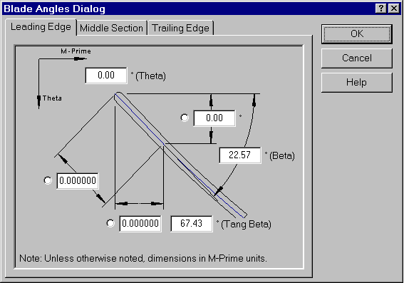
This dialog presents the Blade Angle Parameters for the Leading Edge, Middle Section, and Trailing Edge of the blade. The user can use this to modify the tangential shape of the blade using common parameters of interest.
The Leading Edge tab is used to specify the Blade Angle Parameters for the Leading Edge. The user can specify the blade angle and an optional linear section (using one of three dimensions).
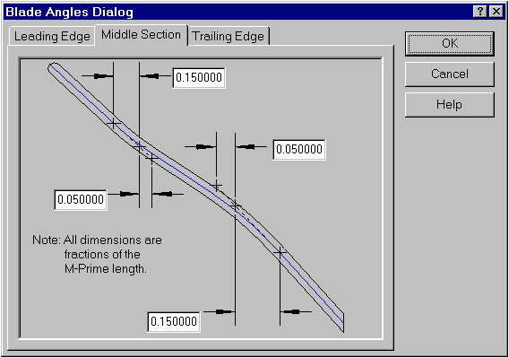
The Middle Section tab is used to specify the Blade Angle Parameters for the Middle Section. The user can specify the location of four (two are optional, enter zero to disable) internal points by the M-Prime length fraction.
The Trailing Edge tab is used to specify the Blade Angle Parameters for the Trailing Edge. The user can specify the blade angle and an optional linear section (using one of three dimensions).
Insert Many Points - Insert points at the location of a left mouse click until selected again.
Insert Point - Add a point at the next left mouse click location.
Insert Point and Split - Insert a point at the next left mouse click location and split the segment there.
Delete Point - Delete the selected point.
Point Location... - Specify the location of the selected point using a dialog box.
Segment Points... - Displays the Point List Dialog to allow editing of all points. Using this dialog, points can be added, modified, and deleted.
Split Segment at Point - Split the segment at the selected point, forming two independent segments.
Join Segment at Point - Join the two segments that share the selected point into a single segment.
Polynomial Order... - Modify the order of the selected Fitted Polynomial Curve segment. The Polynomial Order... command displays a dialog to allow the specification of the polynomial order of the curve.
Tangent to Previous - Toggle the ’Tangent to Previous Segment’ property on/off.
Tangent to Next - Toggle the ’Tangent to Next Segment’ property on/off.
Read Segment Points... - Read the points on the selected segment from a file.
Save Segment Points... - Save the points on the selected segment to a file.
General - Converts the Angle Spanwise Distribution to the General Distribution. The General command converts the Angle Definition to the General Definition, where the user can individually control each layer of the model. This is the standard mode of operation for BladeGen.
Ruled Element - Convert the Angle Spanwise Distribution to a Ruled Element Distribution. The Ruled Element command converts the Angle Definition to a Ruled Element Definition. In this mode, only the hub and shroud curve can be modified. All other layers are controlled by the hub and shroud curve.
Axial Element - Convert the Angle Spanwise Distribution to an Axial Element Distribution. The Axial Element command converts the Angle Definition to an Axial Element Definition. In this mode, only the hub curve can be modified. All other layers are controlled by the hub curve.
Radial Element - Convert Angle Spanwise Distribution to a Radial Element Distribution. The Radial Element command converts the Angle Definition to a Radial Element Definition. In this mode, only the hub curve can be modified. All other layers are controlled by the hub curve.
User-Defined... - Convert Angle Spanwise Distribution to User Defined, driven by the equations entered. The User-Defined... command converts the Angle Definition to User Defined. In this mode, the user can specify how the interpolation from hub to shroud is performed. An equation and variables can be defined by the user which will be used to control all but the hub and shroud layers.
Axial Taper Angle - Used for Mold Release. The Axial Taper Angle... command displays a dialog to allow the user to specify a taper angle in the axial direction. The maximum taper angle is the angle that reduces the blade to 10% of its original thickness at the ’worst’ point.
Meanline (default) - Define the angle data to be located at mean line. The Meanline (default) command declares that the angle view defines the mean line of the blade.
Side 1 - Define the angle data to be located on side 1 (first side encountered using right hand rule). The Side 1 command declares that the angle view defines first side of the blade, where side 1 has smaller theta values than side 2 in a right hand system.
Side 2 - Define the angle data to be located on side 2 (second side encountered using right hand rule). The Side 2 command declares that the angle view defines second side of the blade, where side 1 has smaller theta values than side 2 in a right hand system.
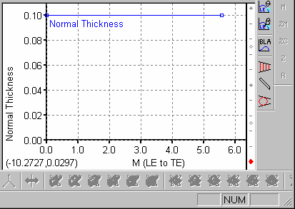
The Thickness View, shown below, describes the total normal or tangential thickness of the blade along a streamline (called a layer). See Thickness View Popup Menu for details of the options and functions available in this view.
The user can modify the data of the curve directly or elect to specify a NACA Airfoil thickness distribution which will be used to create a curve that satisfies the NACA parameters.
The data handled by this view has only a second order affect on the blade surfaces, making the view seem very stable. This is the only view where the piecewise linear segment type is recommended for use.
Point Drag Control Submenu - See Point Drag Control Submenu.
Convert Points to Submenu - See Convert Points to Submenu.
Segment Type Submenu - See Segment Type Submenu.
Segment Operations Submenu - See Segment Operations Submenu.
vs. M-Prime - Set the horizontal axis dimension to radius normalized meridional distance (M’).
vs. % M-Prime - Set the horizontal axis dimension to the percent of the total radius normalized meridional distance (%M’).
vs. M - Set the horizontal axis dimension to meridional distance (M).
vs. % M - Set the horizontal axis dimension to the percent of the total meridional distance (%M).
% Cam vs. % Cam - Set the axes dimensions to thickness as the percent of total camber length (%Ct) vs. location as percent of the total camber length (%C).
NACA Thickness - Display the NACA dialog to allow specification of a NACA thickness distribution and change the thickness display to thickness as percent of camber length vs. location as percent of camber length. See the NACA Dialog for further information on the parameters required.
Show Curve for each Defining Layers - Toggle the display of the thickness curves for all defining layers (other than the current layer) in the background, in gray.
Show Legend - Toggle the display of the legend on/off.
Swap Axes - Swap the horizontal and vertical axes of the selected graph.
Proportional Axes - Toggle the proportionality setting of the graph axes on/off.
Layer Control... - Display the Layer Control Dialog for the current Thickness Definition. The user can create layers and/or check or uncheck the check box to signify which layers will be used for the Thickness Definition. When both new layers are added and current layers are removed, the checked layers are added before the unchecked layers are removed.
Layer Submenu - The Above command changes the displayed layer to the next layer above (by span). The Below command changes the displayed layer to the next layer below (by span). These commands allow rapid changes in the displayed layer, including layers which are not defining layers.
Spanwise Distribution Type Submenu - See Spanwise Distribution Type Submenu.
Thickness View Data Type Submenu - See Thickness View Data Type Submenu.
Copy View Image/Data to Clipboard - Copy the Current View’s Image and/or Data to the Clipboard (in text, bitmap, or metafile formats). This allows transfer of data to reports, spreadsheets, and presentations for documentation of the blade design.
Zoom Fit - Zoom to fit the data within the current view.
Normal to Meanline on Layer Surface (default) - In this mode, the thickness specified in the thickness view is applied from a meanline point, normal to the meanline curve and on the layer surface (a surface of revolution).
Normal to Camber Surface - This option scales the specified thickness by the secant of the local blade lean angle in order to obtain the corresponding thickness measured on the layer surface. This has the effect of a normal-to-camber-surface thickness specification while keeping the computed thickness vector on the layer surface.
Tangential on Layer Surface - When this option is selected, the thickness vector is modified to be purely in the theta direction.
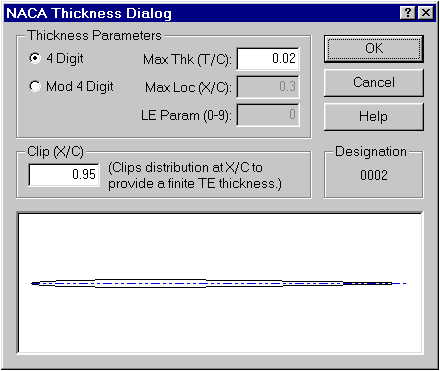
This dialog can be used to specify a thickness distribution to follow a NACA equation. The user requests a NACA Airfoil thickness distribution by selecting the NACA Thickness option from the popup menu in the Thickness View. This dialog allows the user to specify several NACA Airfoil parameters for the active layer.
The Clip (X/C) parameter is used to clip the thickness distribution at a reasonable thickness. The user should avoid specifying 1.0 as this would result in a zero thickness value at the trailing edge.
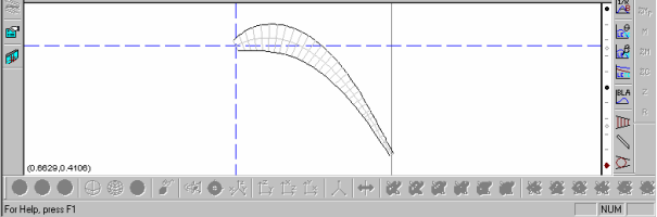
The Pressure/Suction View, shown below, is used to define the two sides of a blade directly. Each side is defined by its own curve, which can be either manipulated directly or adjusted using the Bezier Blade Dialog (Bezier Blade Dialog).