The dialog boxes are shown and described in the following sections:
- 9.3.2.1. Common BladeGen Dialogs
- 9.3.2.2. Initial Setup Dialogs
- 9.3.2.3. Blade Property Dialog
- 9.3.2.4. Point/Layer Control Dialogs
- 9.3.2.5. Meridional View Specific Dialogs
- 9.3.2.6. Angle View Specific Dialogs
- 9.3.2.7. Thickness View Specific Dialogs
- 9.3.2.8. User-Defined Spanwise Distribution
- 9.3.2.9. Pressure/Suction View Specific Dialogs
- 9.3.2.10. Tool and Analysis Dialogs
- 9.3.2.11. 3D View Dialogs
- 9.3.2.12. Curve/Segment/Point Dialogs
- 9.3.2.13. Export Dialogs
- 9.3.2.14. Named Input Dialogs
- 9.3.2.15. Unit Dialogs
- 9.3.2.16. Utility Dialogs
The following topics are discussed:
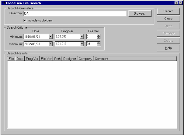
This dialog provides a quick search for native BladeGen files, with search criteria. The search can be performed in a single directory, or include sub-directories.
Once the search has been performed, the user can select one or more files on which to perform the Open, Remove, or Delete functions.
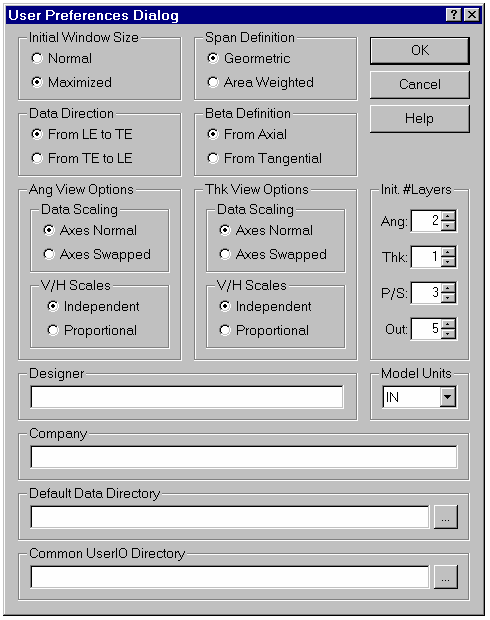
This dialog provides access to user preferences from the File | Preferences menu command.
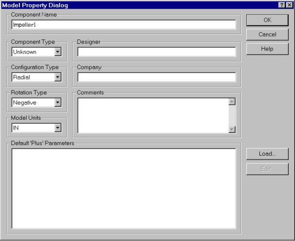
This dialog provides access to the model properties. These include a description of the component, the length units, the name of the designer and company, and a comment field. Access is also provided to the ’Plus’ parameters through the Load and Edit buttons.
If you transfer the geometry to BladeEditor, the Component Name serves to name the resulting BladeEditor blade.
The following topics are discussed:
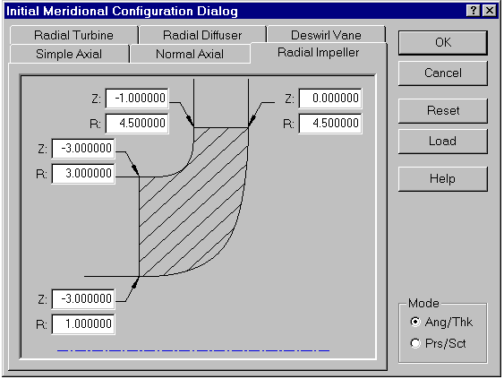
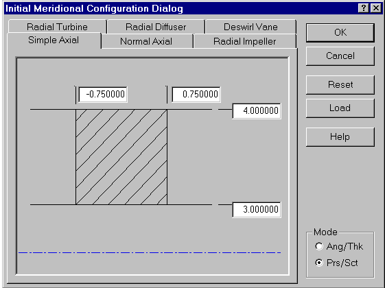
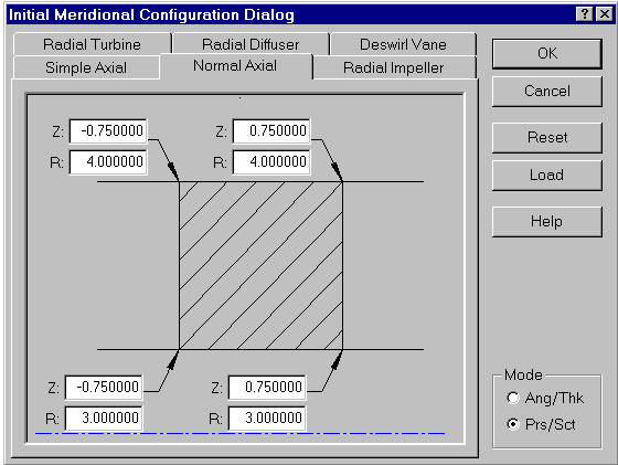
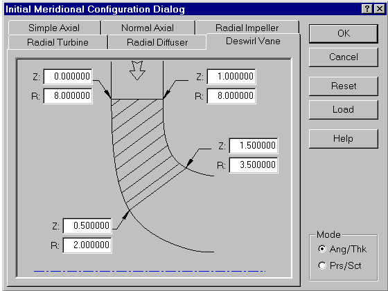
This dialog is used to specify the four corners of the blade in order to initialize the meridional shape.
The Simple Axial tab is used to specify the four corners of the blade in order to initialize the meridional shape.
The Normal Axial tab is used to specify the four corners of the blade in order to initialize the meridional shape.
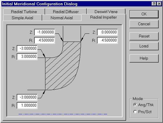
The Radial Impeller tab is used to specify the four corners of the blade in order to initialize the meridional shape.
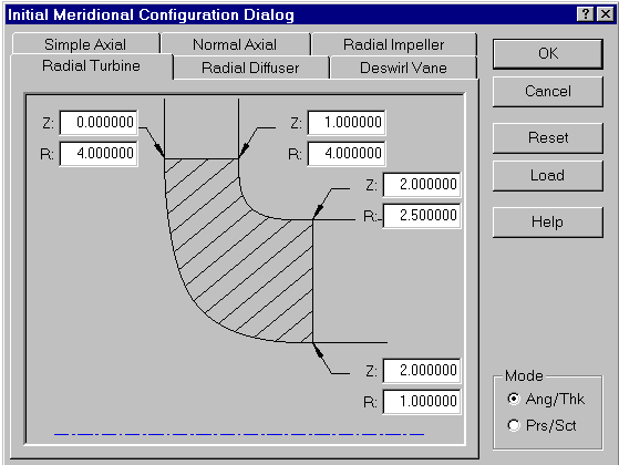
The Radial Turbine tab is used to specify the four corners of the blade in order to initialize the meridional shape.
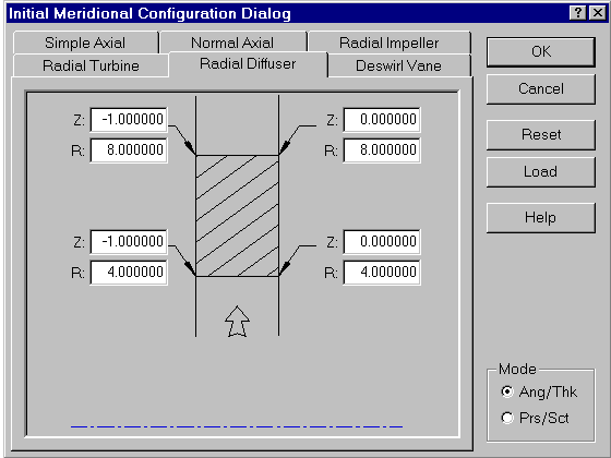
The Radial Diffuser tab is used to specify the four corners of the blade in order to initialize the meridional shape.
The Deswirl Vane tab is used to specify the four corners of the blade in order to initialize the meridional shape.
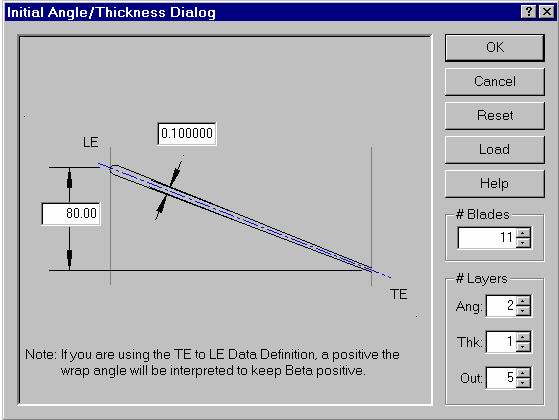
This dialog is used to specify the initial angle and thickness parameters of the blade.
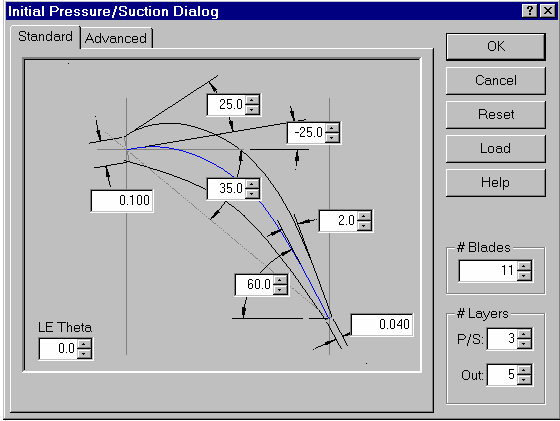
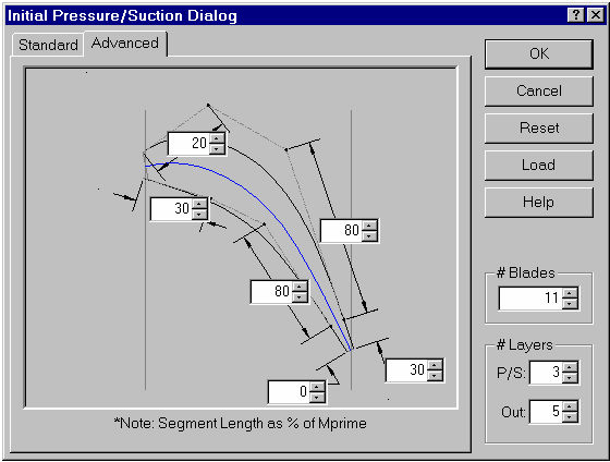
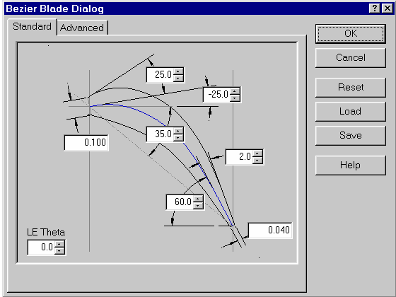
This dialog provides access to the initial shape of a Prs/Sct Side Mode blade based upon common parameters. These include the basic (standard) shape parameters and the advanced curve parameters. These parameters are applied to all layers of the blade.
The Standard tab provides access to the standard shape parameters of the blade.
The Advanced tab provides access to the advanced curve parameters of the blade.
Also See:
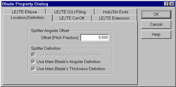
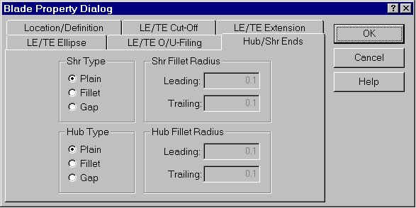
This dialog is displayed when the Blade | Properties menu command is selected or the equivalent toolbar button is pressed. The dialog provides access to all of the Blade Properties from a single access point.
The Location/Definition tab provides access to the parameters associated with splitter blades. Controls are provided to allow positioning of the splitter (pitch fraction) and to determine if the blade uses the main blades definition or has its own independent definition.
The LE/TE Cut-Off tab can be used to cut off a blade.
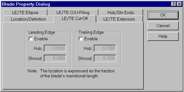
Similarly, the LE/TE Extension tab can be used to extend a blade.
Once a cut-off or extension has been applied, it appears as a curve in the Meridional View. This curve may then be manipulated using any of the tools available for that view. Although any point on the curve may be moved (including an endpoint), one end will always reside on the hub and the other on the shroud.
Note: Cut-offs and extensions are applied after the blade is created and do not change the basic blade definition.
The LE/TE Ellipse tab provides access to the leading and trailing edge end treatment (Ellipse, Cut-off, or Square). The elliptical edge location may be specified using the ’Ellipse Location’ buttons.
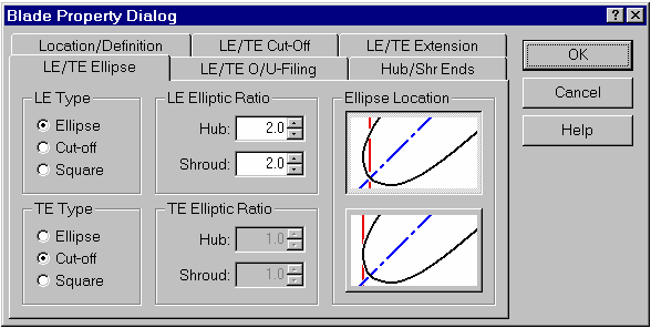
Note: You cannot specify a perfectly sharp trailing edge. As a workaround, you can specify a square trailing edge with a small, but finite, thickness (for example, 0.05 mm).
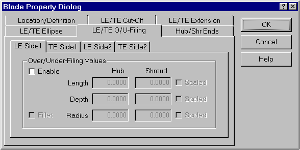
The LE/TE O/U-Filing tab provides access to the over/under-filing properties for each of the four ’corners’ of the blade.
Selecting the Enable control enables the four controls that represent the length and depth at the hub and shroud and fills them with valid initial values. The scaling checkboxes are also enabled for the length and depth.
Selecting the Fillet control (which is not enabled until the Enable control is selected) enables the two controls used to specify the radius at the hub and shroud and fills them with valid initial values. The scaling checkbox is also enabled for the radius.
The checkbox labeled Scaled to the right of each control set specifies how the linear interpolation between hub and shroud values will be performed. If this box is left unchecked, the interpolation is performed directly (linearly), using the values entered. Checking the box specifies that the interpolation should be performed using thickness normalized values. The Scaled option is useful for blades with highly non-linear thickness distributions and will result in thinner sections of the blade having less material removed. Note that end treatments will be applied to the blade before any leading and trailing edge ellipses are generated.
The Hub/Shr Ends tab provides access to the hub and shroud end treatment. The functionality for this tab of the dialog is not implemented.
The following topics are discussed:
This dialog provides access to the number and distribution of point in the mean-line data created in BladeGen.
For details, see Output Point Control.
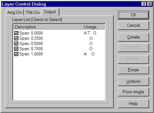
This dialog provides access to the layers of the model. This dialog is re-used to specify which layers are to be used for the Angle, Thickness, Prs/Sct, and Output definition of the model, one at a time.
This dialog allows the user to select a layer’s type and set its parameters. This dialog is used for both initial setup of a layer and modification of a layers properties.
For details, see Layer Dialog.
The following topics are discussed:
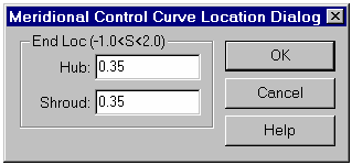
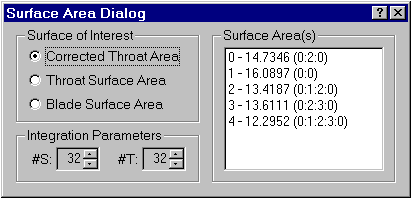
This dialog provides access to the end locations of the control curve, by ’S’ value. The leading edge of the blade is at 0.0 and the trailing edge is at 1.0.
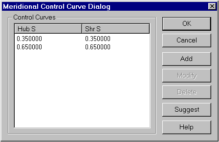
This dialog provides access to the control curves by their hub and shroud ’S’ locations. The user can use this dialog to quickly edit the list of control curves. Finer control can be obtained by dragging end points or inserting and deleting curves from the menu.
The following topics are discussed:
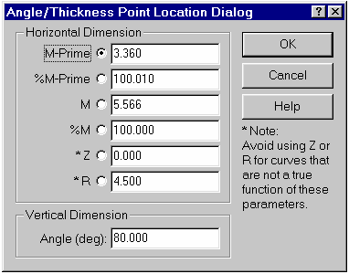
This dialog is displayed when the user requests to modify a point from the Angle or Thickness View. This dialog allows the user to specify the horizontal location of a point using various coordinates.
This dialog presents the Blade Angle Parameters for the Leading Edge, Middle Section, and Trailing Edge of the blade. The user can use this to modify the tangential shape of the blade using common parameters of interest.
For details, see Blade Angles Dialog.
The following topics are discussed:
This dialog can be used to specify a thickness distribution to follow a NACA equation. The user requests a NACA Airfoil thickness distribution by selecting the NACA Thickness option from the popup menu in the Thickness View. This dialog allows the user to specify several NACA Airfoil parameters for the active layer.
For details, see NACA Thickness Dialog.
The following topics are discussed:
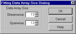
This dialog is used to specify the number of points that are to be collected and stored for use when fitting a User-Defined Spanwise distribution.
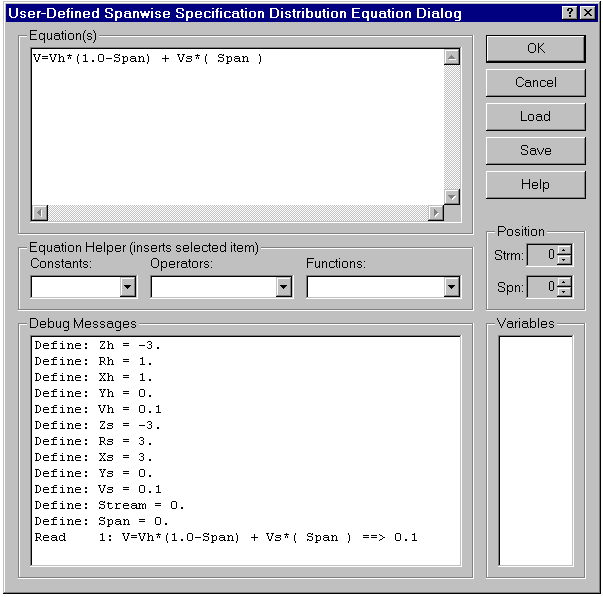
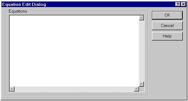
This dialog provides access to the equation which describes a User-Defined Span-wise Distribution.
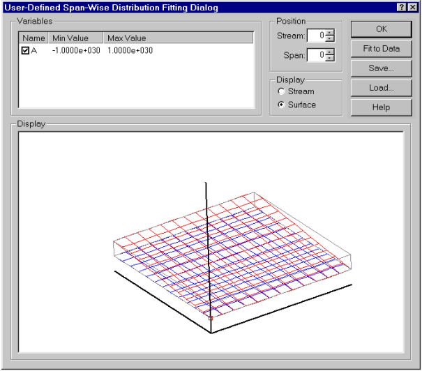
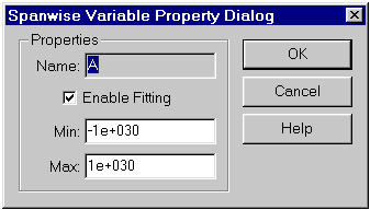
This dialog is displayed to provide access to data fitting functions and control of variable parameters when using a User-Defined Span-wise Distribution.
The following topics are discussed:
This dialog provides access to the shape of a Prs/Sct Side Mode blade based upon common parameters. These include the basic (standard) shape parameters and the advanced curve parameters. These parameters are applied only to the current layer of the blade.
Also See:
The following topics are discussed:
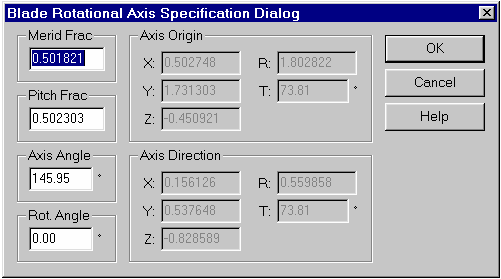
This dialog provides access to the parameters used for the rotation of blades about an axis. Controls are provided for both the definition of the rotation axis and the angle of rotation.
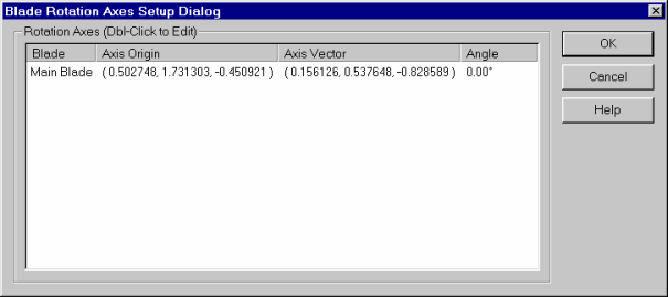
This dialog provides access to each blade’s rotation parameters. Double-click on the blade of interest to access that blades parameters.
The following topics are discussed:
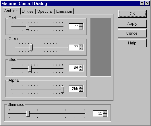
This dialog can be used to modify the appearance of the material when the model is shaded.
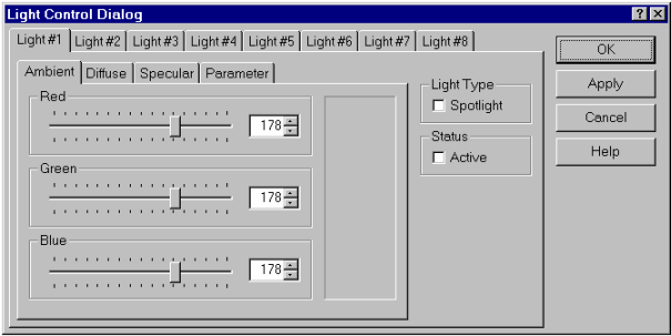
This dialog provides access to the eight lights available in the 3D View. By making selections on the two rows of tabs, the user can access any of the parameters of interest.
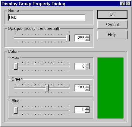
This dialog provides access to the properties of a group used in the 3D view.
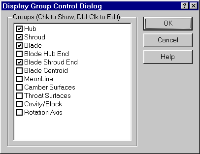
This dialog provides access to the display groups, enabling the user to choose which groups are displays and the parameters used to display them.
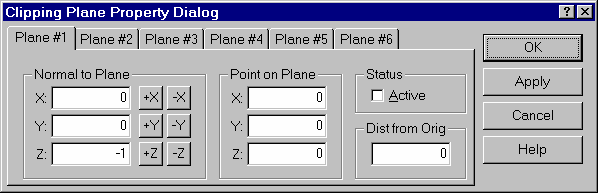
This dialog provides access to the six clipping planes available in the 3D View. These planes are located by a point and oriented by a normal vector.
The following topics are discussed:
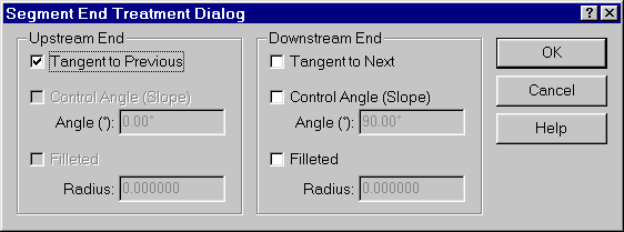
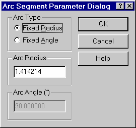
This dialog provides access to the parameters used to control the end treatment of a segment.
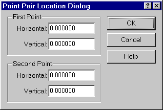
This dialog is used to specify the two points used to reposition a curve.
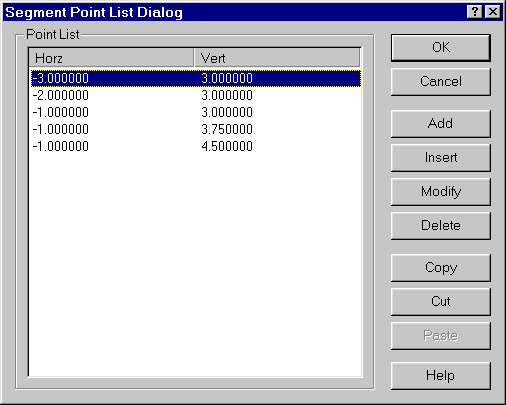
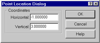
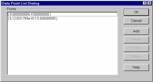
This dialog provides access to the parameters used to locate a point.
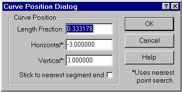
This dialog provides access to the parameters used to locate a point on a curve.
The following topics are discussed:
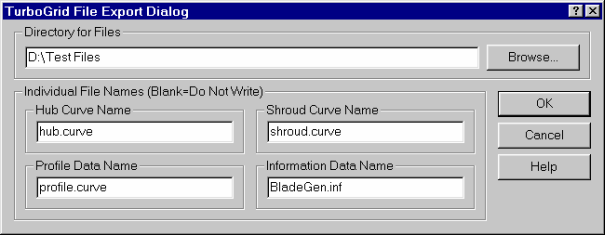
This dialog specifies the directory and file names to be used when exporting a TurboGrid file set.
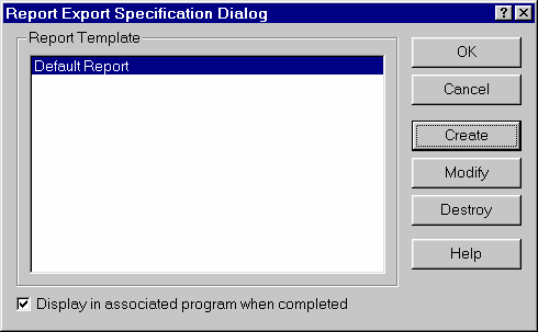
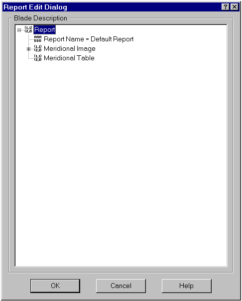
This dialog is used to specify the report template to be used to export a report. The user can also create, modify, or delete templates.
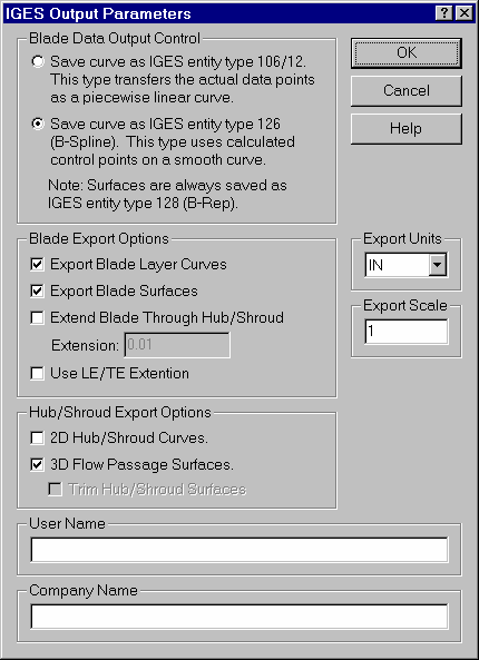
This dialog specifies the options and parameters used to export an IGES file.
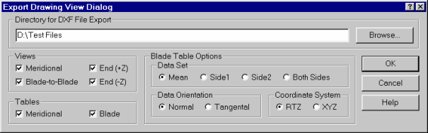
This dialog specifies the parameters used to export 2D DXF views and tables.
The following topics are discussed:
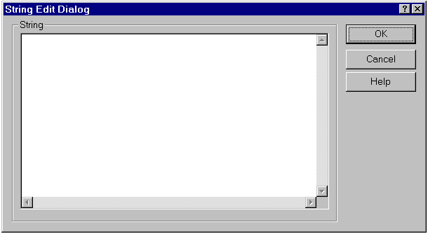
This dialog is used to edit a named input file, such as the report template files (’bgr’). This dialog relies on a context-sensitive popup menu (accessed with a right mouse click) for commands. Editing of BladeGen Input Files (’bgi’) is now handled by a specialized, twin-view window.
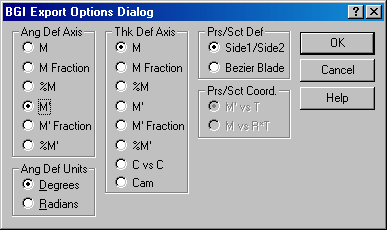
This dialog provides access to variables in a named input file. The user can enter an equation using the pre-defined constants/variables shown below.
The following topics are discussed:
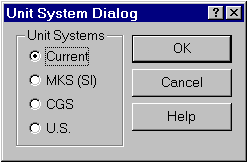
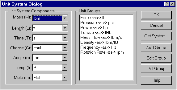
This dialog allows the user to select predefined unit systems for use.
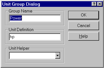
This dialog provides access to the definition of a unit group. The user can use unit groups to specify that specific unit combinations should be displayed in a particular unit. For example, the user can specify that pressure should be displayed as ’psi’.
The following topics are discussed:
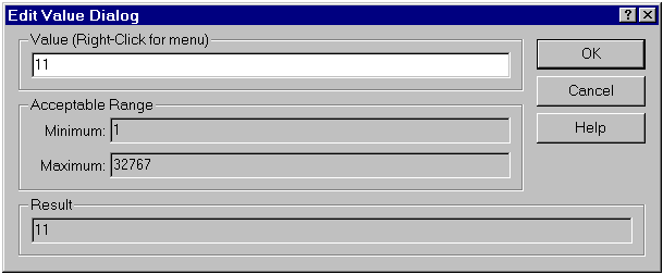
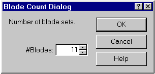
This default dialog is re-used to provide access to integer numbers.
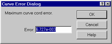
This default dialog is re-used to provide access to floating point numbers.
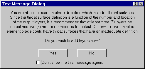
This default dialog is re-used to display various warning messages. The user can choose to hide these messages by checking the check box at the bottom of the dialog.
This dialog displays the version, subversion, and build number of the application.