BladeGen provides a variety of methods for data import/export. They are described in the following sections:
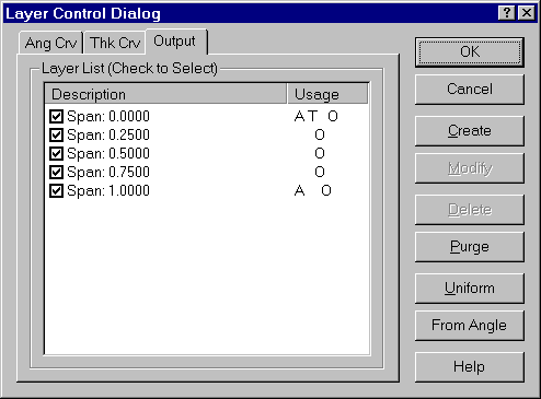
BladeGen allows the user to control which layers are output, and the number of data points included with those layers.
The following topics are discussed:
The Layer Control Dialog allows the user to specify which layers are used for output. It is accessed using either the Model | Output Layer Control menu command or the ![]() toolbar button. Note that these layers can be different than the layers used to define the blade in the angle and thickness views. Pressing the From Angle button in the dialog will cause all layers used in the Angle or Pressure/Suction views (depending on the operating mode) to be flagged for output. For a complete description on the use of layers, refer to Layer Details .
toolbar button. Note that these layers can be different than the layers used to define the blade in the angle and thickness views. Pressing the From Angle button in the dialog will cause all layers used in the Angle or Pressure/Suction views (depending on the operating mode) to be flagged for output. For a complete description on the use of layers, refer to Layer Details .
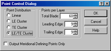
The Point Control Dialog specifies the distribution and number of points to be generated per layer in all export operations. It is accessed from the Output | Output Point Control... menu command or the ![]() toolbar button. If you select Output Meridional Defining Points Only then the Point Distribution and Points per Layer settings are ignored, in which case the only points that will be exported are the defining points. Note that you should not select Output Meridional Defining Points Only when the case involves splitter blades.
toolbar button. If you select Output Meridional Defining Points Only then the Point Distribution and Points per Layer settings are ignored, in which case the only points that will be exported are the defining points. Note that you should not select Output Meridional Defining Points Only when the case involves splitter blades.
In a Trim Meridional Profile has been created, the user can choose to create output using either the Design or Trim Meridional Profile.
|
Sub-Menu Command |
Toolbar Button |
Description |
|---|---|---|
|
Use Design Profile |
|
Uses the Design Profile (curves and layers) to create the output. |
|
Use Trim Profile |
|
Uses the Trim Profile (curves and layers) to create the output. |
The following topics are discussed:
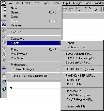
Data can be exported in the following formats using the File | Export menu. Many file types can also be exported using the File | Save As... menu command and selecting the desired type in the File Type control.
Table 9.12: Data Export File Types
|
Format |
Extension |
Description |
|---|---|---|
|
rtf |
Generates a Rich Text Format (.rtf) file containing user-selected plots and tables | |
|
bgi |
Generates an ASCII file containing the model definitions and equations suitable for batch processing. | |
|
curve |
Generates data files of the hub, shroud, and blade contour for TurboGrid. | |
|
dxf |
Generates DXF files for the selected drawing views and tables. | |
|
ibl |
Generates a Pro/ENGINEER ’ibl’ file of the blade(s) and meridional contour. | |
|
dxf |
Generates a DXF file of the blade(s) and meridional contour for import into CAD packages. | |
|
igs |
Generates an IGES file of the blade(s) and meridional contour for import into CAD packages. | |
|
ndf or xml |
|
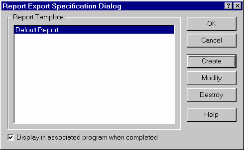
This export option writes a Rich Text Format (.rtf) file containing plots and tables describing the blade design. Using the Report Export Specification Dialog shown below, the user can specify either a default or custom format for the report. The dialog box also enables you to create, modify or delete templates.
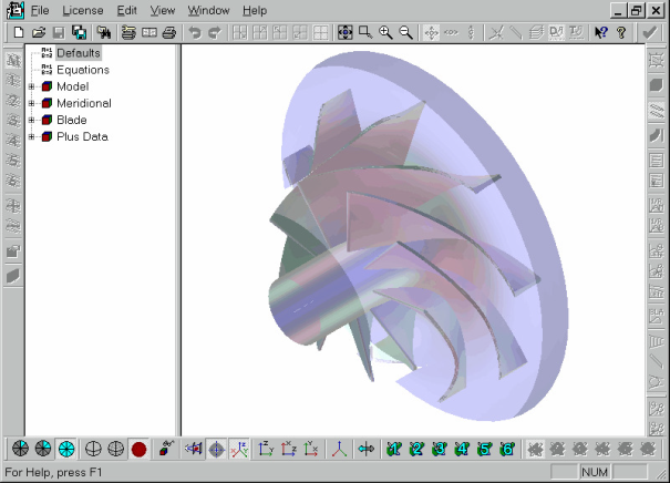
All of the views in BladeGen (Meridional, Angle, Thickness, Pressure/Suction, and Auxiliary Views) are available for inclusion in the report. The underlying data used to describe the working views (Angle, Thickness, and Pressure/Suction) can be included as tables in the report.
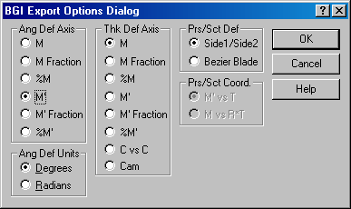
Selecting this export option generates a ’bgi’ file of the current model. The BGI Export Options Dialog, shown below, is displayed to allow the user to specify units and other options before the file is created. After the file is created, the Batch Input Editor Window (also shown below) is displayed.
Related Topics:
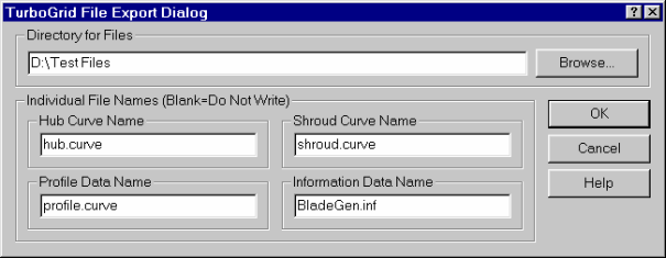
The export type generates the files required by TurboGrid to generate a grid. The TurboGrid File Export Dialog, shown below, is used to control the directory and file names for the data files.
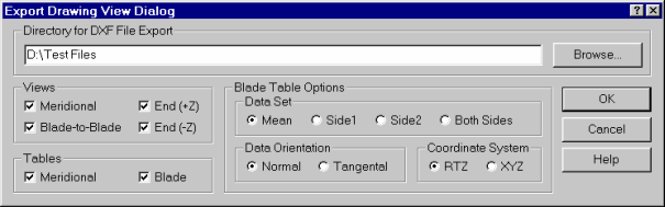
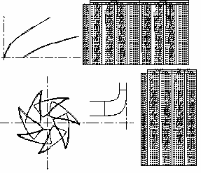
The 2D DXF Drawing Views... menu command exports a series of 2D DXF files. These files can be imported into CAD systems to construct tables and views documenting the blade design. When the export type is chosen, the Export Drawing View Dialog, shown below, is displayed to control the output. The typical views are shown below.
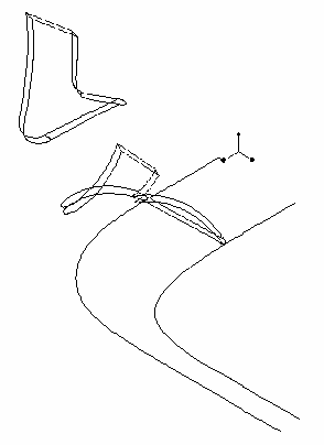
This produces a 3D wireframe in Pro/ENGINEER’s ’ibl’ format, as shown below.

This option produces a 3D wireframe in DXF format, as shown below.
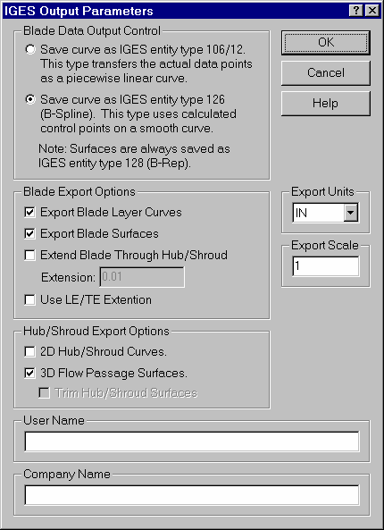
This option produces a 3D model of the current blade system in IGES format. This file can then be imported into CAD packages. The IGES Output Parameters Dialog shown below controls which entities are included in the IGES file.
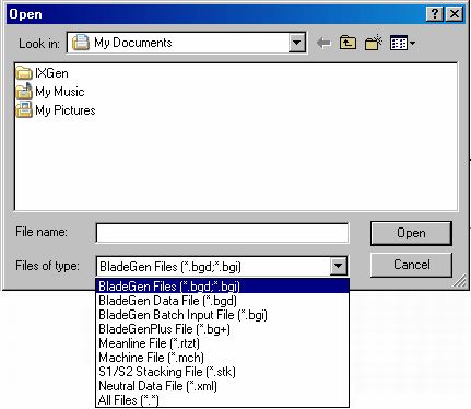
Blades can be imported from, and exported to, files
of type Neutral Data File (*.ndf;*.xml) (also known as NDF files).
Such files, which have the Neutral Data Format, can be written and loaded by BladeGen and BladeEditor.
NDF File Import Details and Limitations
BladeGen can model only one blade row at a time. If the NDF file being loaded contains more than one blade row, BladeGen will prompt you to select a main blade; it will then load the blade row associated with that blade.
The supported length units in the NDF file are: mm, m, cm, in, ft.
BladeGen ignores the angular tolerance specified in the NDF file.
NURBS curves are converted to approximate Bezier curves or approximate cubic splines. An warning is issued when NURBS to cubic spline conversion exists.
A NURBS curve used in a user defined layer contour in an NDF file is converted to a Bezier segment or cubic spline segment, according to built-in heuristics. If the conversion is to a cubic spline segment, the conversion is approximate.
A user defined layer contour in an NDF file may extend beyond the leading edge or trailing edge contours. If the layer contour does not reach the leading edge or trailing edge contours, BladeGen will automatically extend the contours using linear extrapolation.
For interpolated layers, the interpolation type specified in the NDF file is ignored, and interpolation is always done in R*Theta space. A warning message is issued.
Blades (in an NDF file) that are defined using Theta with leading and trailing edge Beta values will have their Beta values set only for the main blade, and for independent splitters having neither leading nor trailing edges cut-off, only if the angle definition (in the NDF file) is a curve consisting of a single Bezier segment with least four control points. For any other blade being imported from an NDF file, the end Beta angles are ignored and a warning message is issued.
NDF File Export Details and Limitations
Model > Mode > Prs/Sct is not supported for NDF export and triggers an error.
Each best fit polynomial curve is converted to a cubic spline. This applies to all instances: Meridional definitions, Angle definitions, and Thickness definitions. A warning message is issued to notify you of any conversions.
Angle/Thickness data is written to NDF files only in the direction of leading edge to trailing edge. If this data is specified from trailing edge to leading edge (Model > Ang/Thk Data Direction > Data from TE to LE) then the direction is converted in the exported NDF file and a warning message is issued.
Meridional trim profiles are not written to the NDF file. A warning message is issued if such profiles exist.
Meridional control curves are not written to the NDF file. The Meridional Control Curves setting is treated as being set to Normal. A warning message is issued if the Meridional Control Curves setting is not set to Normal.
Meridional curve constraints are not supported by the NDF format.
Use Hyperbolic Shape must be Ruled Element Only, otherwise NDF export triggers an error.
Model > Spanwise Calculation must be Geometric. Constant span layers that are calculated using area weighting are not supported for NDF export and trigger an error.
Only constant span layers, data layers and one shroud gap layer, are written into the NDF file for the FlowPath definition. If there are any other layers, they are ignored and a warning message is issued.
The closest shroud gap layer to the hub is treated as a blade tip clearance with specified shroud gap leading edge and trailing edge values. All other shroud gap layers are ignored and a warning message is issued. The shroud gap layer can be a defining layer.
Angle View Data Location must be Meanline (default). The other settings (Side 1 and Side 2) are not supported for NDF export and trigger an error.
The Angle Spanwise Distribution Type of User-Defined is not supported for NDF export and triggers an error.
The Thickness Spanwise Distribution Type of User-Defined is partially supported for NDF export; the "Fit to Data" option is not exported.
End Angle Definition and End Angle with Beta Slope=0 Definition are not supported by NDF. These two types of definitions are converted to Theta Definition and a warning message is issued.
A blade may be defined by Theta alone, or by Theta with leading and trailing edge Beta angles, depending on several factors:
For the main blade, and for independent splitters having neither leading nor trailing edge cut-off, if the angle definition is a curve consisting of a single Bezier segment with least four control points, and slope (Beta angle) constraints are applied to both the leading and trailing edges, the angle definition written to the NDF file includes leading and trailing edge Beta angles.
For all other cases, a Theta definition is created in the NDF file without any specification of leading and trailing edge Beta angles.
Thickness data defined as %Cam vs. %Cam (for example, NACA thickness) is not supported for NDF export and triggers an error.
When a cut-off leading or trailing edge is defined for splitters, the angle definition curve is first trimmed by the cut-off and then converted to a cubic spline curve. The same treatment is applied to the thickness definition curve. In such cases, a warning message is issued.
Blade Properties are supported for NDF export as follows:
For a leading or trailing edge ellipse, the Ellipse Location option must be set to the meanline option, not the tangent option, otherwise NDF export triggers an error.
Over/Under-Filing Values are not supported. NDF export triggers an error if any side of a blade has filing defined.
LE/TE Cut-Off is supported for splitters, but not main blades, in which case NDF export triggers an error.
LE/TE Extension is not supported and causes NDF export to trigger an error.
Hub/Shr Ends is not supported; NDF export ignores these values.
BladeGen now provides a single interface for both import and export. This option provides the user with the highest level of flexibility when it comes to supporting specialized or proprietary file formats.
Several of the file formats previously supported internally have been converted to UserIO modules. These include the Meanline (.rtzt) and Machine (.mch) files. This change demonstrates the capability of the interface and allows users to start with one of these modules and enhance it to meet their needs.
The interface works by identifying the modules which are located in a specific location (the UserIO sub-directory of the installation). These executables are called with a specific command line parameter. If the executable returns the proper data, it is added to a data structure for later use.
All modules configured for export appear in the File | Export sub-menu. Export modules can also indicate that they should be added to the File Save Dialog’s File Type control. Import modules are added to the File Open Dialog’s File Type control.
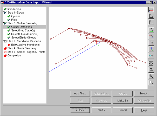
BladeGen provides a general purpose capability for importing data from a variety of sources. The import process involves converting general 3D geometry into a meanline format suitable for BladeGen. The process is initiated by selecting the File | New | Data Import Wizard... menu command.
For further information on this process, please see the Data Import Wizard Guide.