


BladeGen breaks the complex, 3-dimensional (3D) geometry of a blade into two or three 2-dimensional (2D) views. The data from these views is used to create the model, one blade’s layer at a time. These views, plus an auxiliary view, are simultaneously displayed in the BladeGen window and all views use the same set of zoom and pan keyboard shortcuts and mouse actions.
The Annotated BladeGen Window Layout (Figure 9.10: Annotated BladeGen Window Layout (Angle/Thickness Mode)) displays a typical layout of views used by BladeGen. These views will automatically update whenever a change is made. Each element of the user interface is identified in the Annotated BladeGen Window Layout.
Related Topics
BladeGen has two distinct modes of operation, the Angle/Thickness (Ang/Thk) Mode and the Pressure Side/Suction Side (Prs/Sct) Mode. These two modes provide the design environment for radial and axial blades, respectively.
Both modes use a set of Common Views, a Meridional View and an Auxiliary View, which are positioned side by side at the top of the window. The Meridional View is used to define the blade in radial vs. axial space. From this definition, the streamlines are generated which are required for all of the other views. The Auxiliary View provides the user with the display of a Blade-to-Blade View, 3D View, Meridional Contour View and several graphs of various blade parameters.
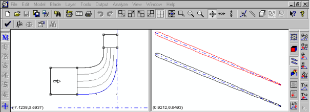
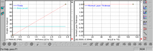
The Ang/Thk Mode uses two views at the bottom of the window; an Angle View for the angular distribution of the blade, and a Thickness View for the thickness distribution of the blade. These views define the blade at discrete streamlines (layers). The data from these two views must be combined with the streamline data to generate the blade’s shape on a layer.
The Prs/Sct Mode adds a single larger Prs/Sct View of the blade at the bottom of the window. This view allows the user to manipulate the pressure and suction sides of the blade to achieve the desired blade shape.
Although the sides of a blade are usually identified as the pressure side and suction side, BladeGen cannot distinguish between these names. BladeGen uses the terminology "Side1" and "Side2" to identify the sides of the blade in increasing theta order (right-hand rule).
Related Topics:
BladeGen allows one or more blades to be defined, where the first blade is the "Main Blade" and subsequent blades are called splitters. Only one blade is active at any one time, but the output always includes all blades. The blades can be defined independently or the splitters can rely on the angle and/or thickness definition of the Main Blade.
Related Topics:
A layer (or streamline) is defined as a meridional curve visible in the Meridional View that represents surface of revolution. Most layer types, shown below, represent curves that are automatically created and updated as the Meridional Envelope (hub and shroud curves, leading and trailing edge curves) are modified.
Layers serve two key purposes:
Layers are referenced by the working views (Angle, Thickness, and Prs/Sct Views) to provide the meridional location of the view’s data sets.
Layers specify where streamline data sets are to be constructed for export.
Table 9.1: Layer Types
|
Layer Type |
Description |
|---|---|
|
Span Layer |
Curve is defined by a constant spanwise position, as specified by a single span fraction. |
|
Hub Gap Layer |
Curve is defined by a normal offset from the hub at a distance specified by a linear interpolation between a leading edge and a trailing edge value. |
|
Shroud Gap Layer |
Curve is defined by a normal offset from the shroud at a distance specified by a linear interpolation between a leading edge and a trailing edge value. |
|
Data Layer |
Curve is initially positioned by a span fraction value, but the user can interactively modify the curve in the Meridional View. This layer type is also used when importing meanline data, as the data may not lie exactly on a streamline. |
|
Hub Offset Layer |
Curve is defined by a Meridional offset (z, r) of the hub curve. |
|
Shroud Offset Layer |
Curve is defined by a Meridional offset (z, r) of the shroud curve. |
Related Topics:
The curves used in BladeGen are made up of one or more segments (sub-curves). Each segment can consist of a different curve type. By allowing different segment types to be combined into a single curve, BladeGen provides the user with more control over the overall curve shape than would be provided with a single-curve-type restriction.
Related Topics:
In the previous sections, the user has been exposed to the concepts of views, blades, layers and curves. The diagram shown below describes the relationships between the user and the model data for the Ang/Thk Mode. The data structure for the Prs/Sct Mode is similar, but the Ang/Thk components are replaced by the Prs/Sct equivalents.
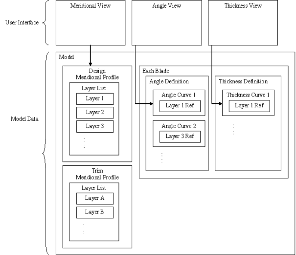
The Model represents the blade system in 3 dimensions. The Model contains the following data:
A Design Meridional Profile, consisting of a set of curves and a list of Layers (curves that represent streamlines).
An optional Trim Meridional Profile with its own set of curves and layers.
One or more Blades. Each Blade consists of an Angle and Thickness definition.
The Angle and Thickness Definitions are made up of Curves that the user can modify. A single Curve in a definition references a single Layer from the Design Meridional Profile’s layer list. The collection of these curves makes up each definition.
The user’s access to the Model Data is provided through the working views (Meridional, Angle, and Thickness). In the Meridional View , the user controls the shape of the layer curves. In the Angle and Thickness Views, the user can modify the definition curve that references the active Layer.
Output is created one Layer at a time. A streamline contains Z, R, M, & M’ a meanline adds q, Tn, & b.
The Design Meridional Profile is used to generate the streamline data for the requested Layer (which may come from either the Design or Trim Meridional Profile).
The Blade’s cut-off (or extension) curves are used to trim the streamline curve.
The angle and thickness data is added to the streamline to create a meanline curve.
Over/Under-Filing is applied to the meanline in the Z vs. R*q coordinate system.
Leading/Trailing edges are applied to the meanline in the Z vs. R*q coordinate system.
These guidelines are included to help users maximize the benefits from using BladeGen.
Users should first define the meridional profile before defining the Ang/Thk or Prs/Sct views, since these views are dependent on the path length of the meridional profile’s layers.
The Angle, Thickness, and Pressure/Suction Views define parameters on a layer (a streamline in the meridional view). The first layer must be the hub and the second must be the shroud, with additional layers inserted at a user-specified fraction of the span. If only one layer is defined, it applies to the entire span between hub and shroud. The Pressure/Suction view requires that both the hub and shroud layers be defined.
All views display the same layer and blade. If a view doesn’t have a definition for a particular layer that is being displayed, the calculated values at that layer are displayed.
The mode (Ang/Thk or Prs/Sct) is determined, initially, by the type of component created or the mode of the model when it was saved. However, the mode can be changed using the Model | Mode | Ang/Thk Mode... or Model | Mode | Prs/Sct Mode... menu commands.