


BladeEditor provides a geometry connection between BladeGen and DesignModeler. Reasons for importing BladeGen blades into DesignModeler include:
BladeGen can output geometry in many different point data formats, but its surface output in IGES format is cumbersome to use.
BladeGen does not produce a solid model in a standardized format such as Parasolid.
You can combine an imported blade with other CAD geometry imported via one of the many DesignModeler-supported CAD file formats.
You can add hub and shroud fillets.
Through BladeEditor, one or more BladeGen models can be linked into a DesignModeler session, so that any changes to the BladeGen models will be reflected in DesignModeler the next time you update the Geometry cell.
When you import a BladeGen model, BladeEditor does the following:
Constructs blade surfaces
Creates a solid model for the blades and hub
Creates 2D sketches for the meridional contours and non-flow-path hub geometry
Creates periodic fluid zones
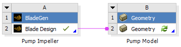
The preferred method of importing a BladeGen file is to create a link from a BladeGen system’s Blade Design cell to a Geometry system’s Geometry cell (representing DesignModeler/BladeEditor).
This link maintains the data transfer relationship between the
two cells. The desired import options should be specified in the Blade Design
cell properties (see Table 9.2: BladeGen Blade Design Cell Properties).
Note that the link can transfer geometry
with either the Load NDF or the Import BGD
data transfer type, as specified in the Blade Design
cell properties.
After you make the link, the Geometry cell should
be updated to process the imported geometry.
Note: If you edit the Geometry cell before updating it, then
the ImportBGD feature details that are shown in BladeEditor may not accurately
reflect the Blade Design cell properties. To refresh the ImportBGD
feature properties, click ![]() in BladeEditor. It is not recommended that you edit the ImportBGD
properties inside BladeEditor because they will be overwritten by the
properties from the Blade Design cell the next time you update the
Geometry cell.
in BladeEditor. It is not recommended that you edit the ImportBGD
properties inside BladeEditor because they will be overwritten by the
properties from the Blade Design cell the next time you update the
Geometry cell.
The following topics are discussed:
As mentioned earlier, a link from a Blade Design cell to a Geometry
cell can transfer BladeGen geometry to BladeEditor with the Load NDF data
transfer type.
The Load NDF data transfer type uses the Neutral Data Format
to pass the blade design details from BladeGen to BladeEditor.
The advantage of using the Load NDF data transfer type
is that BladeEditor creates native blade geometry features that can be modified.
The disadvantage of using the Load NDF data transfer type
is that the model features are limited to those available in BladeEditor. Consequently,
some of the advanced features available in BladeGen cannot
be used with this approach. For details of the restricted features,
see Neutral Data File (NDF File) in the TurboSystem User's Guide.
Note: When updating the geometry from BladeGen, any changes to the following BladeEditor features are not preserved:
Sketch parameters
Angle/thickness curve points
As mentioned earlier, a link from a Blade Design cell to a Geometry
cell can transfer BladeGen geometry to BladeEditor with the Import BGD data
transfer type.
An alternative way to import BladeGen geometry into BladeEditor is to import a BladeGen file from outside the
project. To do this, click ![]() in the BladeEditor toolbar. When you click this icon, you will be
prompted for the location and name of the BladeGen (.bgd) file. Once the filename is selected, the details view enables you
to select the properties for the import. These properties are listed
in Table 10.4: Properties for the ImportBGD Feature. As with other DesignModeler feature
properties, you can double-click in a property value box to change
the selection to the next choice, or single-click the property and
select the value from the drop-down list.
in the BladeEditor toolbar. When you click this icon, you will be
prompted for the location and name of the BladeGen (.bgd) file. Once the filename is selected, the details view enables you
to select the properties for the import. These properties are listed
in Table 10.4: Properties for the ImportBGD Feature. As with other DesignModeler feature
properties, you can double-click in a property value box to change
the selection to the next choice, or single-click the property and
select the value from the drop-down list.
Table 10.4: Properties for the ImportBGD Feature
| Property | Default Value | Function |
|---|---|---|
|
ImportBGD |
ImportBGD# |
This property defines the name of the import feature. |
|
Source |
(selected BGD File) |
This property defines the name and path of the
imported .bgd file. You can change the source
to a new .bgd file if Refresh is set to |
|
Unit Preference |
(default is the DesignModeler length unit) |
You may change the value of this property to
the intended BladeGen model length unit if the latter does not match
the DesignModeler length unit. If the BladeGen model length unit is specified
as " Make sure that the length unit specified here is appropriate for the model. If the BladeGen dimensions are too small, DesignModeler may fail to import the BladeGen model. |
|
Create Hub |
Yes |
If this property
is set to |
|
Hub Offset |
1 (Inch) |
This property defines the default line offset
(in the preferred length unit) for creating the initial Note that this property
is available only if Create Hub is set to |
|
Create Blades |
All |
If this property is set to If this
property is set to |
|
Merge Blade Topology |
Yes |
If this property is set to If this property
is set to |
|
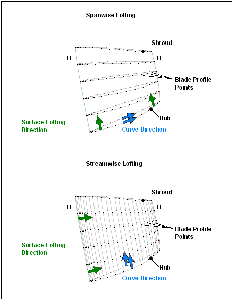
Streamwise |
If this property is set to If this property is set to For an illustration of these lofting methods, see the figure after this table. | |
|
No |
This property specifies whether a shroud
clearance is created. If If If | |
|
Layer Number |
1 |
This property defines the selected layer index for the shroud clearance. Note that this property is available only if Create Shroud Clearance is selected. |
|
Create Fluid Zone |
Yes |
If this property is set to |
|
Yes |
If this property is set to Note that this
property is available only if Create Fluid Zone is set to | |
|
Blade Extension (%) |
2 |
This
property defines the surface extension length (as a percentage of
the average hub to shroud distance) for the blade surfaces. These
surfaces are extended and then trimmed to the |
|
Periodic Surf Extension (%) |
5 |
This property defines
the surface extension length (as a percentage of the average hub to
shroud distance) for the periodic surfaces. These surfaces are extended
to ensure that the |
|
Periodic Surf Style |
Three Pieces |
This property specifies the style of the periodic interface surfaces. If If Note that this property is available only if Create
Fluid Zone is set to |
|
Refresh |
Yes |
This property specifies whether the imported BladeGen model should
remain linked to the DesignModeler session. If this property is set to If this property is set to |
Figure 10.15: Spanwise Lofting versus Streamwise Lofting shows how spanwise lofting and streamwise lofting differ.
Once the properties for the ImportBGD feature have been set, click the button, and the BladeGen model will be imported.
The following features will then be created in the tree view:
MerPlane: this plane is a copy of the Z-X plane; it is the plane on which the blade design sketches are created.MasterProfile: a sketch defining the hub, shroud, leading edge, trailing edge, inflow and outflow boundaries of the blade passage (imported from the .bgd file) will be created. This sketch is used during the creation of the blade bodies, and can be used to create the fluid zone. You should not modify this sketch.[1]BladeProfile: a sketch defining the locations of the leading and trailing edges for the main blade will be created.HubProfile: a sketch defining the hub body will be (optionally) created. This sketch can be modified; however, you should take care to ensure that the sketch loop remains intact or the hub body will fail to regenerate.HubBody- (Optionally) theHubProfilesketch is revolved to create theHubBodyfeature in the tree view.
BladeBody- The blade surface data is imported and lofted in DesignModeler to create theBladeBodyfeature in the tree view.StageFluidZone- (Optionally) theMasterProfilesketch is revolved and cut into a sector by the periodic surface to form theStageFluidZonebody. This feature forms a sector of the fluid volume around a single blade, but the blade has not been removed from the volume.Enclosure- When theStageFluidZoneis created, the blade (and any other connected geometry) is removed from theStageFluidZonebody by theEnclosurefeature.Named Selections - These are the labeled regions on the final Enclosure body:
Blade,Hub,Shroud,Inflow,Outflow,PeriodicAandPeriodicB.
There is a known limitation with the ImportBGD feature when importing multiple BladeGen files. If you have imported two or more BladeGen files using separate ImportBGD features, and have turned on shroud clearance for one of these features, then the import process may fail. The workaround is to import the case(s) with shroud clearance first, then import the others.
Furthermore, changing the Blade Design cell Shroud Clearance property from "Relative Layer" or "Absolute Layer" to "None" will have no effect on the ImportBGD feature. In this case, you must change the Shroud Clearance property directly in the ImportBGD feature.
The following BladeGen model features are incompatible with BladeEditor, and prevent successfully importing a BladeGen case into BladeEditor.
trim profile
[1] This constraint is to prevent the MasterProfile and the blades from becoming inconsistent,
because the blade surface data comes from BladeGen.