This section includes:
The following topics are discussed:
The Method setting enables you to generate an ATM topology in three basic ways.
AutomaticAutomatically selects the appropriate topology based on the blade style (cut-off or rounded edges) and blade angles. The topology family chosen by TurboGrid appears beside ATM Topology > Used.
[Topology Family]Allows you to manually select one of several topology packages, called families. If you have chosen a topology family that does not fit your geometry, you will receive an error message, and the topology will not be generated. For details, see Manually Selecting a Topology Family.
Manual (Advanced)For details, see Advanced Topology Control.
By manually selecting a topology family, you are selecting one of the families that TurboGrid uses to generate a topology.
Load the blade geometry and set the geometry parameters (for example, inlet/output points) as necessary.
Open the Topology Set object.
Click Apply.
Click the Topology Viewer tab.
In ATM Topology > Method, scroll through the options in the drop-down menu to see the different topology families. A description of the family appears in the Topology Viewer (not the 3D Viewer) when the family is selected.
Select the topology family you want to use.
Click Apply.
Right-click Topology Set and clear Suspend Object Updates.
Note: The Undo command cannot properly undo a suspension change (for example, to the Topology Set object); attempting to undo a suspension change can lead to an inconsistent state.
If you have chosen a topology that fits your geometry, the topology will be generated.
You can view the details of the topology, regardless of whether it has been generated, by clicking the Details tab in the Topology Set editor. For more details, see Details Tab for the Topology Set Object.
If you choose a topology that does not fit your geometry, the list of topology families in ATM Topology > Method shrinks to include only the topology that will fit your geometry. You may select one of the topology families displayed in the Method menu and click Apply to generate a topology that fits your geometry.
To use advanced topology control:
Click Edit > Options.
Select Enable Advanced Features and click OK.
Open the Topology Set object and set ATM Topology > Method to
Manual (Advanced).
Note: Advanced features are tested but require an advanced level of understanding to be used.
A list of the available topology templates is displayed in the object editor. Any templates found in the local working directory (instead of the TurboGrid template directory) will be listed in bold text.
Table 10.1: Topology Template Naming Conventions describes the naming conventions used for topologies.
Table 10.1: Topology Template Naming Conventions
|
Naming Convention |
Description |
|---|---|
|
Prefixed with "S1" |
Applies to geometries consisting of a main blade and a single splitter blade |
|
Prefixed with "LP" |
Low passage topology pieces |
|
Prefixed with "MP" |
Main passage topology pieces |
|
Prefixed with "HP" |
High passage topology pieces |
|
Contains "LE" |
Applies to the leading edge of a single bladed geometry |
|
Contains "TE" |
Applies to the trailing edge of a single bladed geometry |
|
Contains "Passage" |
Applies to the area between blades |
Note:
These terms can appear together. For example, the template LEcircleLowPassage covers both the leading edge and passage areas.
The topology templates are "passage centric", that is, they are designed to fit between the blade and a rotated copy of the blade. Before the topology is used, it is transformed to "blade centric" where it is placed around the blade.
You must select a combination of templates that covers the entire passage without overlap.
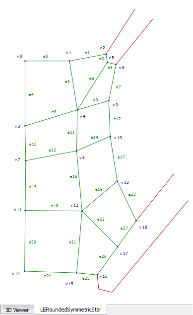
A preview of each topology indicating vertex and edge numbers is provided
to help with the template selection process. Previews appear in the Topology
Viewer when you double-click a topology or when you select a topology and
then click Display Topology
 . For more details, see Details Tab for the Topology Set Object.
In the Topology Viewer, drag the mouse to pan across the image. To zoom in and out, roll the mouse wheel or drag the mouse vertically using the middle mouse button.
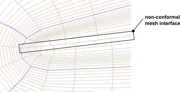
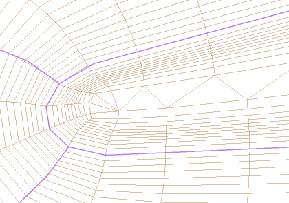
By default, TurboGrid produces a mesh that has a non-conformal mesh interface in the blade tip region. You can select Tip Topology Option > Conformal Tip Enabled to produce a conformal mesh in the tip region that is filled with unstructured wedge elements and that involves no mesh interface.
Note: CCL parameter Conformal Tip Minimum Quad Angle (which can be found by editing the Topology Set object
using the Command Editor dialog box) controls where the unstructured wedge region starts and ends along the blade. Starting from the leading edge
and moving towards the trailing edge (and vice versa), quadrilateral elements (hexahedral elements in the 3D mesh) are used to fill in the space until the minimum inside angle
of a quadrilateral element would drop below the specified value, at which point triangular elements (wedge elements in the 3D mesh) are used to continue filling in the space.
Note that the interior angles of triangular elements may be less than the specified value of Conformal Tip Minimum Quad Angle.
The Split Mesh Regions At Leading Edge option generates a line of rotation from each cut-off point of a "cut-off or square" (see Cut-off or square) blade leading edge. The Split Mesh Regions At Trailing Edge option generates a line of rotation from each cut-off point of a "cut-off or square" blade trailing edge.
A "cut-off or square" edge having the same axial and radial coordinates at both cut-off points will have lines of rotation that coincide. In this case, the applicable option will divide the passage mesh, hub, and shroud at the cut-off edge by a surface of revolution about the machine axis. Additional 2D and 3D regions will be created as a result of this division of the passage. This allows, for example, the mesh to be used in a simulation where the portion of the passage mesh surrounding the blade rotates, while the rest of the passage mesh is stationary.
These options may still be used if the cut-off points do not have the same axial and radial coordinates, although the interface between the divisions will not be a surface of revolution.
The Mesh Generation Mode setting has the following options:
ATM— enables traditional ATM topology.ATM3D— enables the ATM3D meshing approach (see ATM3D), which supports the meshing of high-fidelity geometry (see Meshing High-Fidelity Geometry).ATM v2— supports most functionality offered byATMplus other functionality (see ATM v2).
Note: You can set the ATM3D approach to be used by default by setting a preference. For details see TurboGrid Options.
The following table compares the mesh generation modes:
Table 10.2: Mesh Generation Mode Comparison
ATM | ATM3D | ATM v2 |
|---|---|---|
Meshing with high-fidelity geometry is not supported. | Meshing with high-fidelity geometry is supported. | Meshing with high-fidelity geometry is supported. |
Cut-off leading/trailing edges are supported. | Cut-off leading/trailing edges are not supported. | Cut-off leading/trailing edges are supported only if not meshing with high-fidelity geometry. |
Square trailing edges can be approximated using high curvature. | Square trailing edges are not supported. | Square trailing edges are supported (for example, for hydro turbines such as Kaplan and Francis). |
The Details tab lists the topology templates that are being used in the current case.
To display one of the listed topology templates in the Topology Viewer, you can do any of the following:
Right-click a listed topology template and select the Display Topology context menu command.
Select a listed topology template and then click Display Topology
.Double-click a listed topology template.
In the Topology Viewer, blue labels are used to indicate topology nodes and green labels are used to indicate topology edges. Blades are outlined in red. As an example, the figure below shows the LERoundedSymmetricStar topology template: