


Some turbomachinery designs have complex geometric features within the main passage.
TurboGrid has support for meshing complex geometric features at blade ends. You can use the complex blade end high-fidelity geometric feature to mesh various complex tips, including partial tips, squealer tips, and true blade blends.
Figure 12.1: Inlet Guide Vane with Partial Tip Clearance shows an example of a blade with partial tip clearance.
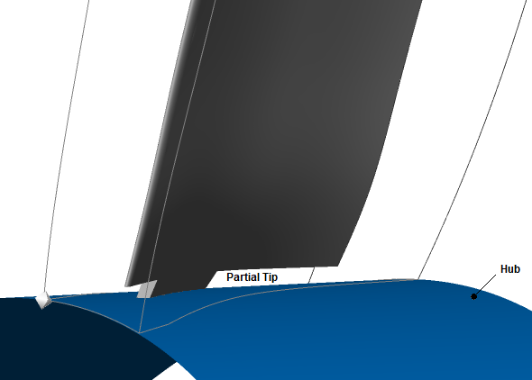
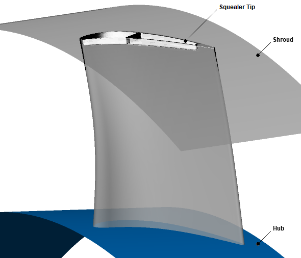
Figure 12.2: Turbine Rotor with Squealer Tip shows an example of a blade with a squealer tip.
Meshing complex blade ends involves using a high-fidelity geometry definition of the blade, hub, and shroud, provided by CAD data.
Meshing with high-fidelity geometry involves a hybrid meshing approach, with blocks of unstructured meshes surrounding high-fidelity geometric features and blocks of structured meshes filling the remainder of the blade passage.
Note: Meshing with high-fidelity geometry is not currently supported for multi-blade cases.
The following topics are discussed:
- 12.1. General Procedure for Meshing of Low-Fidelity and High-Fidelity Geometry
- 12.2. Sources of High-Fidelity Geometry for TurboGrid
- 12.3. Associating CAD Objects in TurboGrid’s Geometry Workspace
- 12.4. Using ATM3D or ATM v2
- 12.5. Working with Meshes for High-Fidelity Geometry in TurboGrid’s Mesh Workspace
- 12.6. Analyzing the Mesh
- 12.7. Saving the Mesh