


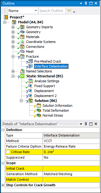
Simulates the separation of two materials across an interface.
 |
Object Properties
The Details Pane for this object includes the following properties.
| Category | Properties/Options/Descriptions |
|---|---|
|
Definition |
Type: Read-only field that describes the object - Interface Delamination. Method: Specifies the formulation used to introduce the fracture mechanism, either Virtual Crack Closure Technique (VCCT - default) or Cohesive Zone Material (CZM). Failure Criteria Option: Options include:
Material: Displays when is the specified as Method. It provides a fly-out menu for Material selection or specification. Material definitions are created in Engineering Data. Suppressed: Excludes the object in the analysis. |
|
Scope |
Initial Crack: Displays when is specified as Method. Select a user-defined Pre-Meshed Crack. Generation Method: Specify as either Matched Meshing or Node Matching. If interface layers imported from Ansys Composite PrepPost (ACP) application are available, a third option, Pre-Generated Interface is also available. This property is automatically set to Pre-Generated Interface for Interface Delamination objects automatically generated during the import process for the interface layers. Scoping Method: Displayed when Node Matching is specified as the Generation Method. Options include Geometry Selection (default) and Named Selection. Specifies that the Source and Target properties are defined using the graphical selection tools or that the geometry is defined by from a drop-down list of available user–defined Named Selections. This option assumes that the existing mesh is already matched. Source: Displayed when Node Matching is specified as the Generation Method. Specify the face on the model that will be the source. Target: Displayed when Node Matching is specified as the Generation Method. Specify the face on the model that will be the target. Match Control: Displayed when Matched Meshing is specified as the Generation Method. The Match Control property references a pre-defined Mesh Match Control. The pre-defined Match Control requires two independent parts that have the same (brick) element/node pattern. Interface (ACP Only): Only available when you create your composite geometry in the ACP application. Select the appropriate Interface Layer from the provided drop-down menu. |
|
Step Controls for Crack Growth |
Displays when is specified as Method. It provides the following properties. If Auto Time Stepping is set to the time step properties can be modified, otherwise they are read-only. Auto Time Stepping: Options include Program Controlled (default) or Manual. Initial Time Step: Initial time step when crack growth initiates. Minimum Time Step: Minimum time step for subsequent crack growth. Maximum Time Step: Maximum time step for subsequent crack growth. |
|
Node Matching Tolerance |
Displays when is specified as Generation Method. It provides the following properties. Tolerance Type: Options include Program Controlled (default) or Manual. Distance Tolerance: Can be modified when the Tolerance Type is set to Manual, otherwise it is read-only - that is, the value is defined by the application. Node matching requires that each node has a corresponding mate (Source and Target). This tolerance value defines the search radius for determining the matching between Source and Target nodes. |
Tree Dependencies
Insertion Methods
Use any of the following methods after highlighting Fracture object:
Click the option on the Fracture Context Tab.
Right-click the Fracture object, Interface Delamination object, or Contact Debonding object and select .
Right-click Options
In addition to common right-click options, relevant right-click options for this object include:
Insert >
Suppress
API Reference
See the Interface Delamination section of the ACT API Reference Guide for specific scripting information.
Additional Related Information
See the following sections for more information: