


Defines a crack that is based on a previously generated mesh and used to analyze crack fronts based on a Named Selection.
 |
Object Properties
The Details Pane properties for this object include the following.
| Category | Properties/Options/Descriptions |
|---|---|
|
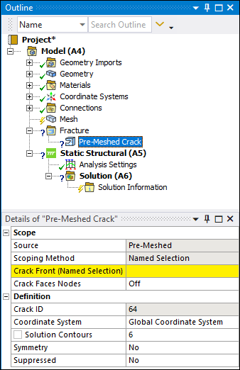
Scope |
Source: Read-only field indicating the type of crack definition. Scoping Method: Read-only and always set to Named Selection when defining pre-meshed cracks. Crack Tip (Named Selection): Assign the scoping of the Pre-Meshed Crack to a valid Named Selection. Click in the Named Selection field and select a node-based named selection. This option is only applicable to 2D analysis. Crack Front (Named Selection): Assign the scoping of the Pre-Meshed Crack to a valid Named Selection. Click in the Named Selection field and select a named selection consisting of nodes. This option is only applicable to 3D analysis. Crack Faces Nodes: Turn this property to specify the crack top face and bottom face node-based Named Selections. The default setting is . This option is only applicable to 3D analysis. When set to , the following additional properties display:
|
|
Definition |
Crack ID: A read-only property that displays a unique system generated identification number ID for the crack object. The application uses this identifier when creating solution identifiers for fracture parameters. Coordinate System: Specifies the coordinate system that defines the position and orientation of the crack. The Y axis of the specified coordinate system defines the crack surface normal. The origin of the coordinate system represents the open side of the crack. You can select the default coordinate system or a local coordinate system that you have defined. The default is the Global Coordinate System. The valid coordinate system must be of type Cartesian. Solution Contours: Specifies the number of contours for which you want to compute the fracture result parameters. Symmetry: Specifies the crack symmetry about a line (in 2D analysis) or about a plane (in 3D analysis). The default is . Suppressed: Toggles suppression of the Pre-Meshed Crack object on and off. The default is No. The Pre-Meshed Crack object is suppressed automatically if the scoped named selection is suppressed. |
Tree Dependencies
Insertion Methods
Select the Fracture object and select the Pre-Meshed Crack option from the Crack group on the Fracture Context Tab. You can also right-click the Fracture object and select the crack from the menu. Any currently inserted cracks also provide this right-click menu.
Right-click Options
In addition to common right-click options, relevant right-click options for this object include:
Insert >
Arbitrary Crack
Semi-Elliptical Crack
Elliptical Crack
Ring Crack
Corner Crack
Edge Crack
Through Crack
Cylindrical Crack
Pre-Meshed Crack
Crack Initiation
Commands
Suppress
API Reference
See the Pre-Meshed Crack section of the ACT API Reference Guide for specific scripting information.