|
Simulation Settings
|
Additive Process: The Additive Process Type - Laser
Powder Bed Fusion. The LPBF process uses thermal energy from a laser or electron
beam to selectively fuse powder in a powder bed.
Inherent Strain: Yes or No. If Yes, the AM
simulation uses a static structural system and the loading strains are calculated
based on an experimentally calibrated Strain Scaling Factor. If No, the AM
simulation uses a linked thermal-structural system in which strains are calculated
from temperature-dependent material
properties and loads. The remaining options under Machine Settings differ
depending on whether Inherent Strain = Yes or No.
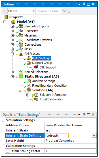
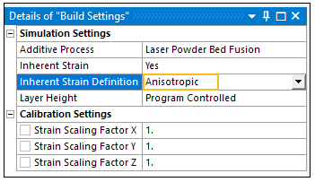
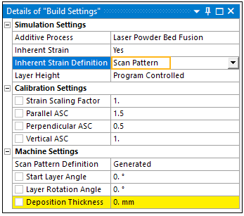
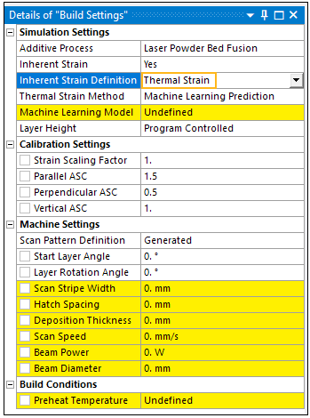
If Inherent Strain = : Inherent Strain Definition:
Isotropic, Anisotropic, Scan Pattern, or Thermal Strain.
assumes that a constant,
uniform strain occurs at every location within a part as it is being
built. uses the same average strain
magnitude as isotropic strain, but it subdivides that strain into
anisotropic components in the X, Y, and Z directions based on the Global
coordinate system. uses the same average strain
magnitude as isotropic strain, but it subdivides that strain into
anisotropic components based on the local orientation of scan vectors
within the part. Scan vectors may be generated internally via a slicing
function assuming a rotating stripe scan pattern or input via a build file. is a method that provides
the highest level of fidelity and takes thermal cycling into account at
each location within the part.
Thermal Strain Method: At this release, only the
Machine Learning Prediction method is available. uses a
machine learning model prediction of the anisotropic Thermal Strain
simulation result from the Ansys Additive application.—Thermal Strain
simulations provide the highest level of fidelity by predicting how
thermal cycling affects strain accumulation at each location within a
part. The simulation follows the full laser path on every layer, and is
based on the machine process parameters (power, scan speed, beam
diameter, etc.)—The machine learning model has been trained to
predict the Thermal Strain result much faster than simulation. It can be
one to three orders of magnitude faster than Thermal Strain simulation
in Additive Print in calculating the strain that is passed to the structural
solver. Speedup increases with part size, scan area, and melt pool size.
See Thermal Strain - Anisotropic in the Additive Print and Science User's Guide and Understanding Machine Learning Thermal Strain.
Machine
Learning Model: A list of materials that were used to
train the ML prediction. Choose the material that most closely matches your
material assignment in Engineering Data. ML models may be based on different
material properties than those in Engineering Data. The ML models are used to
generate loading strains. Materials in Engineering Data are used for the
structural analysis. Layer Height: Sets the element layer height for the
mesh, which must conform to uniform layer sizes in the global Z direction.
Options include (default) and
. For Program Controlled, the application
finds the first layered tetrahedrons mesh method that is scoped to the AM
build body and sets the Layer Height to the value specified in the Details
pane of the layered tetrahedrons mesh method. If there are no layered
tetrahedrons meshes present/scoped to the build, then no Layer Height value is
used. When set to Manual, the user specified Layer Height is used, regardless
of whether a layered tetrahedrons mesh is present.
|
|
Calibration Settings
|
Strain Scaling Factor(s): A calibration factor, or factors,
used to account for differences in additive machines and materials that you may use
to improve the accuracy of your simulations. The SSF scales the inherent strains in
the analysis by the given value. If Inherent Strain = : If Inherent Strain Definition =
, a constant Strain Scaling Factor
may be entered to scale strain everywhere uniformly. If Inherent Strain Definition =
, individual Strain Scaling
Factors may be entered for X, Y, and Z directions based on the Global
coordinate system. If Inherent Strain Definition =
or , individual Strain Scaling Factors, called
anisotropic scaling factors (ASC), may be entered based on the local
orientation of scan vectors within the part, that is, parallel and
perpendicular to scanning direction and in the build direction.
If Inherent Strain = :
|
|
Machine Settings
|
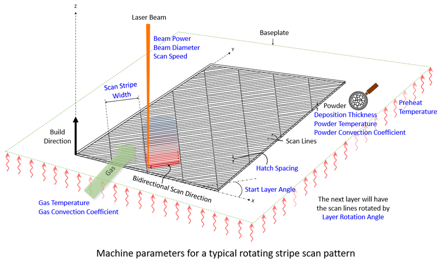
Properties in this category are illustrated in the following figure:
If Inherent Strain = : Scan Pattern Definition (visible if Inherent Strain
Definition = Scan Pattern or Thermal Strain): How the scan pattern is defined,
either generated using a rotating stripe
pattern (default) or input via a build file. Generated: Start Layer Angle and Layer Rotation Angle as defined
below. Scan Stripe Width is also visible if Inherent Strain Definition =
Thermal Strain. These inputs define an internally generated scan
pattern. Build File: Machine Type and Build File Path inputs become available
with this option. These inputs specify an external build file to be used. Machine Type: Specifies the machine or OEM associated with the
build file specified. Options are Additive Industries, EOS, HB3D,
Renishaw, Sisma, SLM, and Trumpf. Build File Path: Location of a .zip file containing the scan
pattern file(s), and an stl of the part geometry. Build files for simulations that use the Machine Learning
Prediction Thermal Strain Method only support
stripe scan patterns. See Build File Requirements in the LPBF Simulation Guide for
additional requirements.
Start Layer Angle: The orientation of fill rasters on
the first layer of the part. It is measured from the X axis, such that 0
degrees results in scan lines parallel to the X axis. The starting layer angle
is commonly set to 57 degrees. Must be between 0 and 180°. Layer Rotation Angle: The angle at which the major
scan vector orientation changes from layer to layer. It is commonly 67
degrees. Must be between 0 and 180°. Scan Stripe Width: When using the stripe pattern for
scan strategy, the geometry can be broken up into sections, called stripes.
The stripes are scanned sequentially to break up what would otherwise be very
long continuous scan vectors. Slicing Stripe Width is commonly set to 10 mm
wide.
Must
be between 1 and 100 mm. Hatch Spacing: The average distance between adjacent
scan vectors when rastering back and forth with the laser. Hatch spacing
should allow for a slight overlap of scan vector tracks such that some of the
material re-melts to ensure full coverage of solid material. For Machine
Learning strain definition, must be between 60 and 1000 microns. Deposition Thickness: The thickness of added powder
material in every pass of the recoater blade. Specifically, use the amount the
base plate drops between layers. For Thermal Strain strain definition, must be
between 10 and 100 microns. Scan Speed: The average speed at which the laser spot
moves across the powder bed along a scan vector to melt material, excluding
jump speeds and ramp up and down speeds. For Thermal Strain strain definition,
must be between 350 and 2500 mm/sec and the recommended range is between 500
and 2500 mm/sec. Beam Power: The power setting for the laser in the
machine. Must be between 50 and 700 Watts. The recommended range is between 50
and 500 Watts. Beam Diameter: The width of the laser on the powder
or substrate surface defined using the D4σ beam diameter definition.
Usually this value is provided by the machine manufacturer. Sometimes called
laser spot diameter. Must be between 20 and 140 µm. The recommended range
is between 80 and 120 µm.
If Inherent Strain = : Heating Method: Controls how new layers are heated in
the transient thermal analysis. Choose Melting Temperature (default) or Power. Heating Duration: Visible if Heating Method = Power.
The amount of time the heat is applied, either Scan Time (default) or Flash. Scan Time: Heat is applied for the
amount of time it takes to scan the volume of material in each element
layer. This setting may give better temperature results at the end of
the layer but may not yield a temperature spike above melting. Note that
this Scan Time option will have a different end time of the simulation
because the layer thickness adjustment for cooling will not be
used. Flash: Heat is applied in a very
short time increment resulting in a spike in temperature then cooling
before the next element layer is added.
Beam Power: Visible if Heating Method =
Power. The power of the laser. Absorptivity: Visible if Heating Method = Power. The
average fraction of energy that is absorbed by the deposited material and
contributes to the heating process. Must be between 0 and 1. Defaults to
0.35. Hatch Spacing: See above. Deposition Thickness: See above. Scan Speed: See above. Dwell Time: The span of time from the end of the
deposition of a layer to the start of the deposition of the next layer. It
includes the time required for recoater-blade repositioning and powder-layer
spreading. Dwell Time Multiple: The dwell-time multiplier
accounts for more than one part in the build. If they are the same part
arranged in the same orientation on the build plate, the multiplier is the
number of parts. Number of Heat Sources: For multiple-beam printers,
specifies the number of beams. This divides the amount of time it takes to
scan a layer by the number of heat sources specified.
|
|
Build Conditions
|
Preheat Temperature: The starting temperature of the
build plate. Used when Inherent Strain = Yes and Inherent Strain Definition =
Thermal Strain, and when Inherent Strain = No. For Thermal Strain strain definition,
must be between 20 and 500 °C and the recommended range is between 20 and 200
°C.
If Inherent Strain = : Gas/Powder Temperature: Options include
(default) and
. Gas Convection Coefficient: Convection coefficient
from the part to the enclosure gas. The convection is applied only to the top
of a newly laid layer. Gas Temperature: Temperature of the gas in the build
enclosure. Powder Convection Coefficient: Effective convection
coefficient from the sides of the part to the powder bed. To estimate, divide
the conduction property of the powder by a characteristic conduction length
into the powder (for example, a quarter of the distance from the part boundary
to the build-chamber wall). Powder Temperature: Temperature of the newly added
powder. Powder Property Factor: The application uses this
factor to estimate the powder properties. The application applies the factor
to the solid material properties to estimate the properties of the material in
its powder state. The powder-state properties are used during the heating of
the new layer (before its subsequent solidification and cooldown) prior to the
next layer being applied.
|
|
Cooldown Conditions
(Inherent Strain = No option
only)
|
Room Temperature
Gas/Powder Temperature: Options include (default) and .
Gas Convection Coefficient: Convection coefficient from
the part to the enclosure gas. The convection is applied only to the top of a
newly laid layer.
Gas Temperature: Temperature of the gas in the build
enclosure.
Powder Convection Coefficient: Effective convection
coefficient from the part to the powder bed. To estimate, divide the conduction
property of the powder by a characteristic conduction length into the powder (for
example, a quarter of the distance from the part boundary to the build-chamber
wall).
Powder Temperature: Temperature of the newly added
powder.
|