


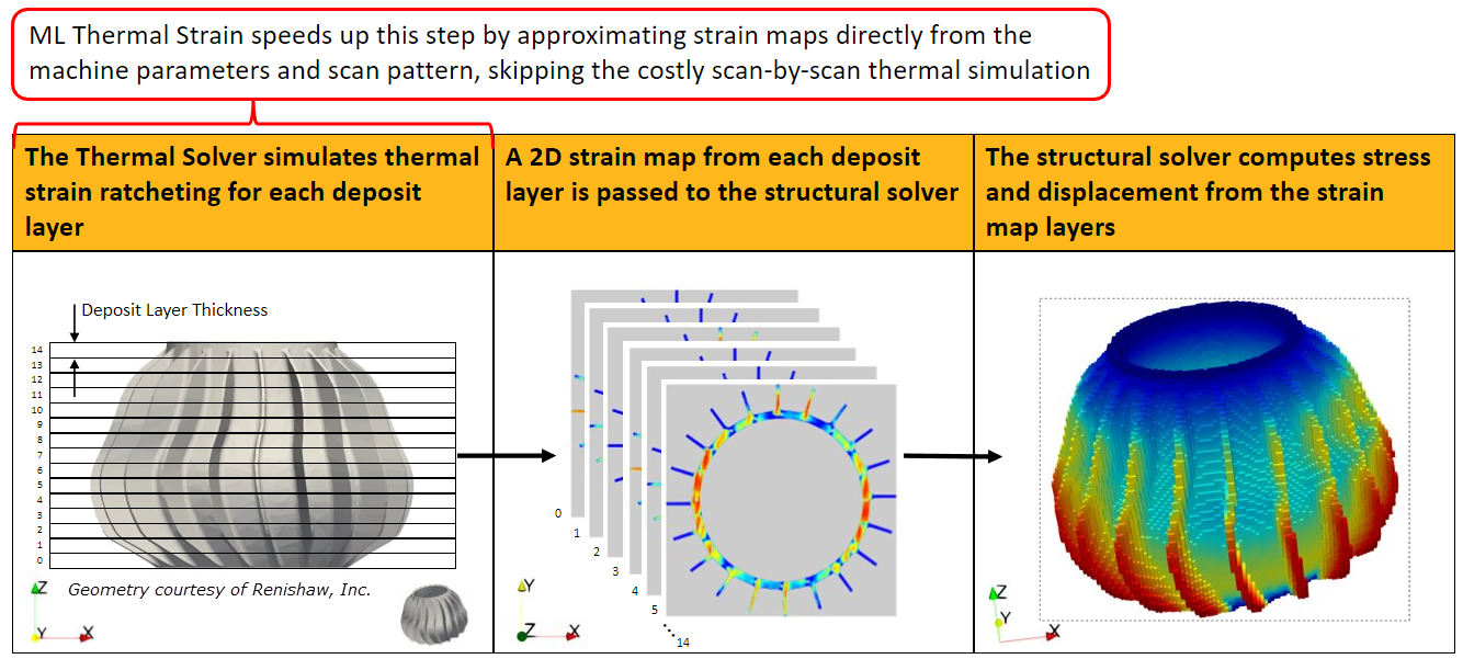
Thermal Strain simulations, specifically those run using Additive Print's Thermal Strain simulation type, provide the highest level of fidelity at the cost of a much longer computational time. That is because Thermal Strain simulations predict how thermal cycling affects strain accumulation at each location within a part. The simulation follows the laser moving along each scan track on each deposit layer and is based on the machine process parameters (power, scan speed, beam diameter, etc.). See Thermal Strain - Anisotropic and Overview of the Thermal Solver in the Additive Print and Science User's Guide.
It can take millions of laser scan tracks to build a typical part with the laser powder bed fusion process, and performing a thermal simulation that follows the laser along each scan track can easily incur a computational cost that is prohibitive. Modern machine learning (ML) techniques provide a way to map from the machine parameters and scan pattern directly to the final outcome, skipping the costly scan-by-scan thermal simulation while providing a high-fidelity result that is computationally practical. Our ML Thermal Strain model, based upon the Thermal Strain simulation type in Additive Print and implemented in Mechanical, predicts the Thermal Strain result much faster than simulation. It can be one to three orders of magnitude faster than Thermal Strain simulation in calculating the strain that is passed to the structural solver. Speedup increases with part size, scan area, and melt pool size.
The ML model is based on a deep convolutional neural network that has been trained on an extensive database of Thermal Strain simulation results. No further data generation or training is required to use ML Thermal Strain. The database used to pre-train the ML model consisted of nearly one million layers from a variety of complex geometries. Machine parameters covered the entire range available when defining build settings, and were restricted to combinations with predicted single bead melt pool dimensions that meet the following constraints:
Single bead melt pool depth must be greater than or equal to deposition thickness
Single bead melt pool width must be greater than or equal to hatch spacing
Single bead melt pool width divided by single bead melt pool depth must be greater than or equal to 1.25
When using ML Thermal Strain, violations of predicted single bead melt pool dimension constraints will trigger messages that recommend how to adjust machine parameters to resolve the violations. Note that the predicted single bead melt pool dimensions are an approximation and may not match results from a Single Bead simulation in Additive Science.
Porosity is neglected. All locations within the part are assigned at least the base strain. For this reason, and because the ML model is subject to error in approximating Thermal Strain results, ML Thermal Strain results may not be an exact match with Thermal Strain results.
We recommend you perform a Strain Scaling Factor calibration specifically for ML Thermal Strain. Do not use Strain Scaling Factor calibration that was completed for Thermal Strain.
Important: The Machine Learning Prediction feature requires a Structures AI+ license.
Frequently Asked Questions
How much of a speedup over Thermal Strain simulation can I expect when I choose ML Thermal Strain?
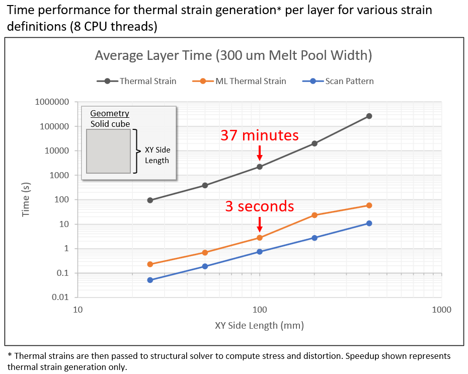
The following plot shows performance data for generating the thermal strain for one deposit layer in a sample part run in various strain modes in the Additive application. For an average layer time of 1 second, it would take ~1000 seconds for a 1000-layer part to complete the thermal strain mapping for the part. Overall, the speedup of strain generation with ML Thermal-Strain can be up to three orders of magnitude faster than Thermal Strain simulation and is comparable in speed to the Scan Pattern simulation type. Speedup increases with part size, scan area, and melt pool size. However, it is important to remember that the speedup from ML Thermal Strain is applicable to the thermal portion only of the overall simulation, and that the thermal strains are then passed to the structural solver to determine stress and deformation. To determine the overall simulation time, you need to add the time taken to solve the structural portion.
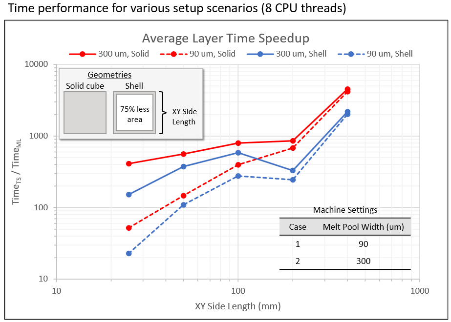
The following plot demonstrates that the speedup of ML Thermal Strain over Thermal Strain simulation improves with increasing part size, scan area, and melt pool size. Melt pool width generally increases as energy is input to the system, such as by increasing power and/or beam diameter, and/or decreasing scan speed. As in the above plot, the data is from the generation of thermal strain for one deposit layer, and this data is from two sample parts with two sets of process parameters run in the Additive application. You can see a 20X to 4500X speedup in these scenarios.
Is the ML Thermal Strain capable of simulating my unique geometry without additional training?
Yes. Additional training is not needed. The ML model was trained with a collection of over 300 parts representing a wide range of geometries including organic shapes, bulky and thin features, state transitions, spiral and helical geometries, and many more.
Is there a limited range of machine input parameters I should stay within?
Yes. The table below shows the required ranges and recommended ranges, if applicable, for the machine parameters required for the ML model.
Parameter Required Range Recommended Range Beam Power 50 to 700 Watts 50 to 500 Watts Scan Speed 350 to 2500 mm/sec 500 to 2500 mm/sec Beam Diameter 20 to 140 µm 80 to 120 µm Deposition Thickness 10 to 100 µm Hatch Spacing 60[a] to 1000 µm Scan Stripe Width 1 to 100 mm Start Layer Angle 0 to 180° Layer Rotation Angle 0 to 180° Preheat Temperature 20 to 500 °C 20 to 200 °C [a] Different than Thermal Strain in Ansys Additive
What if I want to customize my material properties?
Since there are no material property inputs to the ML Model, we can only provide thermal strain results based on the material properties used to train the models. These are the materials validated for the Additive application. Choose the thermal Strain Material Model that most closely matches your material and then be sure to perform a calibration for ML Thermal Strain.
Why do I need to calibrate specifically for ML Thermal Strain? Are there any special considerations for ML when performing a calibration?
Each simulation type represents a specific set of underlying assumptions. For example, an Inherent Strain simulation with an Isotropic strain definition (referred to as the Assumed Strain simulation type in Additive Print) is the most simplifying assumption about strain behavior within a part during a build. More inputs are needed as the underlying assumptions become more complex for various simulation types. A calibration process determines the factor(s) that work with any given set of assumptions to get the best fit to your machine/material/part scenario. Therefore we recommend you perform a calibration for each simulation type you will be performing. See Additive Calibration - Full Procedure in the Additive Print and Science Calibration Guide. While the ML model was based on the Thermal Strain simulation type in Additive Print, we do not guarantee that the ML model, as trained, will always remain in sync with the Thermal Strain simulation type, as occasional tunings of the Thermal Solver are performed.
There are no special considerations for ML when building a calibration part and taking measurements, but be sure to choose ML Thermal Strain in Mechanical when running the simulation portion of the calibration procedure.
Just as we state for all simulation types, it is not necessary to perform a calibration for ML Thermal Strain if your goal is simply to examine trends, that is, the effects of variable changes on stress or distortion relative to each other.