


Go directly to procedural steps.
In this step, specify the simulation and strain assumptions, process parameters, and conditions related to the machine and the process.
Simulation Settings
Simulation settings include assumptions about the type of simulation and the strain definition.
Additive Process: Laser Powder Bed Fusion. The Laser Powder Bed Fusion (LPBF) process uses thermal energy from a laser or electron beam to selectively fuse powder in a powder bed.
Inherent Strain (Yes or No): An option to use the Inherent Strain method. (If you used one of the AM custom systems in Workbench to set up your analysis system, this option is set automatically for you.) If No, the AM simulation uses a linked thermal-structural system in which strains are calculated from material properties and thermal loads. If Yes, an alternative method is used in which strains are based on an experimentally calibrated Strain Scaling Factor. Options under Machine Settings, Calibration Settings, Build Conditions, and Cooldown Conditions differ depending on whether Inherent Strain = Yes or No.
If Inherent Strain = (default if AM Inherent Strain custom system is used):
Inherent Strain Definition: Assumption about strain behavior reflecting the different ways inherent strain is calculated as an input to the structural solver.
Isotropic: Simplifying assumption that a constant, isotropic strain occurs at every location within a part as it is being built. A constant Strain Scaling Factor may be used to scale strain everywhere uniformly to account for calibration of the Mechanical application to a particular machine/material combination.
Anisotropic: Uses the same average strain magnitude as isotropic strain, but it subdivides that strain into anisotropic components in the X, Y, and Z directions based on the Global coordinate system.
Scan Pattern: Uses the same average strain magnitude as isotropic strain, but it subdivides that strain into anisotropic components based on the local orientation of scan vectors within the part. Scan vectors may be generated internally via a slicing function assuming a rotating stripe scan pattern or input via a build file.
Thermal Strain: A method that provides the highest level of fidelity and takes thermal cycling into account at each location within the part.
Thermal Strain Method: Machine Learning Prediction (only method available at this release)
Uses a machine learning model prediction of the anisotropic Thermal Strain simulation result from the Ansys Additive application.—Thermal Strain simulations provide the highest level of fidelity by predicting how thermal cycling affects strain accumulation at each location within a part. The simulation follows the full laser path on every layer, and is based on the machine process parameters (power, scan speed, beam diameter, etc.).—The machine learning model has been trained to predict the Thermal Strain result much faster than simulation. It can be one to three orders of magnitude faster than Thermal Strain simulation in Additive Print in calculating the strain that is passed to the structural solver. Speedup increases with part size, scan area, and melt pool size. See Thermal Strain - Anisotropic in the Additive Print and Science User's Guide.
Important: The Machine Learning Prediction feature requires a Structures AI+ license.
Machine Learning Model: A list of materials that were used to train the ML prediction, in particular, the materials validated for the Additive application. Choose the material that most closely matches your material assignment in Engineering Data. ML models may be based on different material properties than those in Engineering Data. The ML models are used to generate loading strains. Materials in Engineering Data are used for the structural analysis.
Layer Height: By default, the program uses the Layer Height specified when meshing as the super layer height. Occasionally you may want to increase the size of the super layer to something coarser than what was used when you created the mesh. Use the Layer Height option here to do that. Specifying a new Layer Height does not affect the existing mesh.
Calibration Settings
Strain Scaling Factors are optional inputs that scale the inherent strains in an inherent strain simulation, or the thermal strains in a thermal-structural simulation, by a given value. They are usually determined from calibration experiments. Defaults are shown below for the various strain definitions:
| Strain Definition | Strain Scaling Factor(s) | Default Value |
|---|---|---|
| Thermal-Structural simulation | Thermal Strain Scaling Factor | 1 |
| Isotropic - Uniform strain in all directions | Strain Scaling Factor | 1 |
| Anisotropic - Strain can be scaled based on the Global coordinate system | Strain Scaling Factor X Strain Scaling Factor Y Strain Scaling Factor Z | 1 1 1 |
| Scan Pattern and Thermal Strain - Strain can be scaled based on the local orientation of scan vectors (parallel and perpendicular to scanning direction and in the build direction) | Parallel ASC[a] Perpendicular ASC Vertical ASC | 1.5 0.5 1 |
[a] ASC = Anisotropic Strain Coefficient
Machine Settings
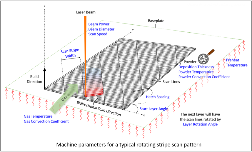
Machine settings refer to process parameters for your AM machine setup. Inputs for machine settings are used to calculate the real, physical time duration of the build process so that the cooldown time can be determined. Every simulation except a simple isotropic Inherent Strain simulation uses some, or all, of the parameters shown in blue in the following figure and defined below.
| Input Parameter | Definition |
|---|---|
| Heating Method | A simulation assumption related to how the material is heated for each new element layer as it is added (made alive). Choose either Melting Temperature (default) or Power. Visible for simulations with thermal solves only (i.e., not Inherent Strain). See Build Settings for details. |
| Start Layer Angle | The orientation of fill rasters on the first layer of the part. It is measured from the X axis, such that 0 degrees results in scan lines parallel to the X axis. The starting layer angle is commonly set to 57 degrees. Must be between 0 and 180°. |
| Layer Rotation Angle | The angle at which the major scan vector orientation changes from layer to layer. It is commonly 67 degrees. Must be between 0 and 180°. |
| Scan Stripe Width | When using the stripe pattern for scan strategy, the geometry can be broken up into sections, called stripes. The stripes are scanned sequentially to break up what would otherwise be very long continuous scan vectors. Slicing Stripe Width is commonly set to 10 mm wide. Must be between 1 and 100 mm. |
| Hatch Spacing | The average distance between adjacent scan vectors when rastering back and forth with the laser. Hatch spacing should allow for a slight overlap of scan vector tracks such that some of the material re-melts to ensure full coverage of solid material. For Machine Learning strain definition, must be between 60 and 1000 microns. |
| Deposition Thickness | The thickness of added powder material in every pass of the recoater blade. Specifically, use the amount the base plate drops between layers. For Thermal Strain strain definition, must be between 10 and 100 microns. |
| Scan Speed | The average speed at which the laser spot moves across the powder bed along a scan vector to melt material, excluding jump speeds and ramp up and down speeds. For Thermal Strain strain definition, must be between 350 and 2500 mm/sec and the recommended range is between 500 and 2500 mm/sec. |
| Beam Power | The power setting for the laser in the machine. Must be between 50 and 700 Watts. The recommended range is between 50 and 500 Watts. |
| Beam Diameter | The width of the laser on the powder or substrate surface defined using the D4σ beam diameter definition. Usually this value is provided by the machine manufacturer. Sometimes called laser spot diameter. Must be between 20 and 140 µm. The recommended range is between 80 and 120 µm. |
If Inherent Strain = (default if AM Inherent Strain custom system is used):
Scan Pattern Definition (visible if Inherent Strain Definition = Scan Pattern or Thermal Strain): How the scan pattern is defined, either generated using a rotating stripe pattern (default) or input via a build file.
Generated: Start Layer Angle and Layer Rotation Angle as defined above. Scan Stripe Width is also visible if Inherent Strain Definition = Thermal Strain. These inputs define an internally generated scan pattern.
Build File: Machine Type and Build File Path inputs become available with this option. These inputs specify an external build file to be used.
Machine Type: Specifies the machine or OEM associated with the build file specified. Options are Additive Industries, EOS, HB3D, Renishaw, Sisma, SLM, and Trumpf.
Build File Path: Location of a .zip file containing the scan pattern file(s), and an stl of the part geometry. See Build File Requirements.
Beam Diameter, Beam Power, Deposition Thickness, Hatch Spacing, and Scan Speed as defined above. If a build file is specified for Scan Pattern Definition, deposition thickness is determined from the file.
If Inherent Strain = (default unless AM Inherent Strain custom system is used):
Hatch Spacing, Deposition Thickness, and Scan Speed as defined above.
Dwell Time: The span of time from the end of the laser scan of one layer to the start of the laser scan of the next layer. It includes the time required for recoater-blade repositioning and powder-layer spreading.
Dwell Time Multiplier: The dwell-time multiplier accounts for more than one part in the build. If they are the same part arranged in the same orientation on the build plate, the multiplier is the number of parts.
Number of Heat Sources: For multiple-beam printers, specifies the number of lasers. This divides the amount of time it takes to scan a layer by the number of heat sources specified.
Build Conditions
Build conditions are the settings pertaining to the environment in the build chamber around the part as it is being printed, including the preheat temperature. For Inherent Strain = , only preheat temperature is required and only with Inherent Strain Definition = Thermal Strain. For Inherent Strain = , additional inputs are required to account for convection.
During a laser powder bed fusion (LPBF) print process, almost all the heat dissipation is conducted through the part back to the build plate rather than out through the unmelted powder surrounding the part. Many users ignore the small effect of heat loss through powder but you may choose to model it as equivalent heat convection.
The Gas/Powder Temperature option allows the use of Preheat Temperature for Gas Temperature and Powder Temperature.
| Input Parameter | Definition |
|---|---|
| Preheat Temperature | The starting temperature of the build plate. Used when Inherent Strain = Yes and Inherent Strain Definition = Thermal Strain, and when Inherent Strain = No. For Thermal Strain strain definition, must be between 20 and 500 °C and the recommended range is between 20 and 200 °C. |
| Gas Temperature | Temperature of the gas in the build enclosure. |
| Gas Convection Coefficient | Convection coefficient from the part to the enclosure gas. The convection is applied only to the top of a newly laid layer. |
| Powder Temperature | Temperature of the newly added powder. |
| Powder Convection Coefficient | Effective convection coefficient from the sides of the part to the powder bed. To estimate, divide the conduction property of the powder by a characteristic conduction length into the powder (for example, a quarter of the distance from the part boundary to the build-chamber wall). |
| Powder Property Factor | A knockdown factor used to estimate the powder properties. The Mechanical application
applies the factor to the solid material properties to estimate the properties of the
material in its powder state. The powder-state properties are used in the newly added layer
during the heating of the new layer (before its subsequent solidification and cooldown) prior
to the next layer being applied. The default value is 0.01. This powder knockdown factor is also used if powder is explicitly modeled in the build. |
Cooldown Conditions
Cooldown conditions are the settings pertaining to the environment in the build chamber around the part in the cooldown step after the last layer is printed. Available only if Inherent Strain = .
Room Temperature
Gas Temperature, Gas Convection Coefficient, Powder Temperature, and Powder Convection Coefficient as defined above, with an option to use Room Temperature for Gas Temperature and Powder Temperature.
Procedural Steps
You can go back to Workbench and select the Engineering Data tab at any time to see properties for your chosen material.
Select the Build Settings object (under AM Process object).
In Details, enter values for all the items under Simulation Settings, Calibration Settings, Machine Settings, Build Conditions, and Cooldown Conditions. You can load a pre-saved file of build settings if you have one – right-click Build Settings and select Load Build Settings. (We provide generic sample files for our AM materials in the ANSYS Inc directory, for example: C:\Program Files\ANSYS Inc\v231\aisol\DesignSpace\DSPages\SampleData\AdditiveManufacturing. In this example, v231 indicates Release 2023 R1. Note that the ANSYS Inc directory on your machine may not be on the C drive.)
Right-click the Build Settings object and select Save Build Settings to save your inputs to an .xml file that can be reused.
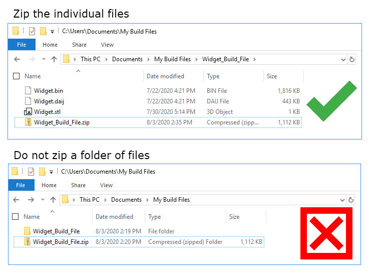
Build File Requirements
Listed here are the general requirements for build files, which are the same as those required for Additive Print. Additional machine-specific requirements are provided in the expandable topics below the general requirements.
We define a build file as a .zip file containing, at a minimum: one .stl file for the part geometry and one machine-specific print file defining the scan vectors. Supported machine manufacturers include Additive Industries, EOS, HB3D, Renishaw, Sisma, SLM, and Trumpf. Ansys may add additional options as we continue to work with more machine partners.
Build files from Additive Prep are automatically created with a file name of "ansys_additive_print.zip.
The build file is a .zip file. Do not nest the files to be zipped within a folder, as a folder structure is not readable. Rather, zip the individual files together as shown in the following figure.
General requirements for the part geometry stl file
Stl files within the .zip file must have units of mm and be positioned in the same location as the part in Mechanical.
Multiple parts can be used, but they must all be within one stl file.
The baseplate should not be included in the part geometry stl file.
Supports should not be included in the part geometry stl file nor as a separate stl file.
General requirements for the machine file
One laser head is assumed for the simulation. Build files with multiple lasers are not supported. When you import a build file with multiple lasers, the application handles it differently depending on the machine. In most cases, the application either generates an error or ignores the extra lasers upon import.
One set of process parameters is used in the simulation. If the build file contains multiple parameter sets, such as different scan speeds and laser powers for the part hatches versus the support hatches, the part hatch parameters will take precedence.
Only one part layer thickness (Deposition Thickness) is allowed.
Only one support layer thickness is allowed, and it must be equal to, or a multiple of, the part layer thickness.
Regardless of how they are defined in the build file, the scan sequence is always simulated from the inside out, that is, from hatch to contour scans. However, the appropriate order is maintained within the hatch area and within a contour. For example, if the build file order is: contour line 1 → contour line 2 → hatch line 1 → hatch line 2, it will be changed to be hatch line 1 → hatch line 2 → contour line 1 → contour line 2.
Scan vectors marked as contour will not be simulated. The definition of contour/hatch is established by the software that creates the build file. If contour-like scan vectors are marked as hatch they will be simulated and results may not be as expected.
Build files for simulations that use the Machine Learning Prediction strain definition only support stripe scan patterns.
Additive Industries Build Files
A build file for an Additive Industries machine should be a zip file containing:
Part = *.stl file
Two machine files are required, one *.daij file and one *.bin file.
Notes:
Support scan vectors will be ignored and will not be simulated. An Additive Industries build file with supports has not been tested.
Only a stripe scan pattern has been tested.
EOS Build Files
A build file for an EOS machine should be a zip file containing:
Part = *.stl file
Machine = *.openjz file. Mechanical uses version 2.8 of the EOS API.
Notes:
You must have an EOSPRINT 2 license, in the form of a dongle or from a license server, from EOS in order to import an EOS build file.. If you are using a dongle, do not unplug it until the after strains have been generated.
EOS M100, M290 and M400 single-laser machines are supported.
Known Issues and Limitations
When preparing the .openjz file in EOSPRINT, start height and end height (<height> element) should not be zero since it is never the position of any layer. The build file may fail to generate strains in Mechanical.
When attempting to import an older EOS build file, the application may reject it since version 2.8 of the EOS API is stricter in regards to the OpenJob format. If this happens, you may see an error.
HB3D Build Files
A build file for an HB3D machine should be a zip file containing:
Part = *.stl file
Machine = *.h3d file. Mechanical uses version 1.0 of the *.h3d file specification.
Notes:
An HB3D build file ignores the last layer when the distance from its Z coordinate to the Z max is less than one layer thickness.
Renishaw Build Files
A build file for a Renishaw machine should be a zip file containing:
Part = *.stl file
Machine = *.mtt file. Mechanical uses version 1.06 of the *.mtt file specification.
Sisma Build Files
A build file for a Sisma machine should be a zip file containing:
Part = *.stl file
Machine = *.wza file. Mechanical uses version 3.0.9 of the *.wza file specification.
SLM Build Files
A build file for an SLM Solutions machine should be a zip file containing:
Part = *.stl file
Machine = *.slm file. Mechanical uses version 1.10 of the *.slm file specification.
Trumpf Build Files
A build file for an Trumpf machine should be a zip file containing:
Part = *.stl file
Machine = *.wza file. Mechanical uses version 3.0.9 of the *.wza file specification.