


Specify a criterion for determining when the application introduces a crack into a specific region (or zone) of the geometry. You can also specify the location, orientation, and the size of the elliptical crack to be initiated.
 |
Object Properties
The Details Pane properties for this object include the following.
| Category | Properties/Options/Descriptions |
|---|---|
|
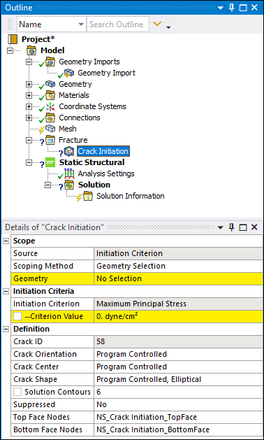
Scope |
Source: Read-only property set to Initiation Criterion Scoping Method: Options include Geometry Selection (default) and Named Selection. Geometry: Use selection filters to pick geometry or nodes, click in the Geometry field, then click Apply. Supported geometry/mesh selections include edge, face, body, and nodes. Named Selection: Select a desired Named Selection from the drop-down menu. You can use either edge-, face-, body-, or node--based Named Selections. Important: For successful crack initiation, make sure that your scoping, whether Geometry or Named Selection, has contiguous nodes, which can be connected into a single patch. |
|
Initiation Criterion |
Initiation Criterion: Read-only property set to . Criterion Value: Specify the value. The application uses the maximum principal stress as the criterion for determining when a crack is initiated. The maximum principal stress values are calculated at every finite element node and are compared with the critical Criterion Value. Once the specified critical Criterion Value is reached, the crack is initiated. You can parameterize this property. Note: If the Criterion Value is not satisfied or not reached, crack initiation will not be successful. In this case, fracture results will be unavailable. You can suppress Fracture Tool (if included) and evaluate other regular results. |
|
Definition |
Crack ID: A read-only property that displays a unique system generated identification value. The application uses this identifier when creating solution identifiers for fracture parameters. Crack Orientation: Specify the orientation type for the crack to be initiated. Options include:
Crack Center: Specify the Crack Center type. Options include (default) and . When you select , the application selects the crack center. When you select , coordinate properties (X/Y/Z Coordinate) display enabling you to specify the coordinates for the desired center of the crack. You can parameterize these individual properties. Crack Shape: Specify the Crack Shape type. Options include (default) and . Currently, only the elliptical crack shape is supported. As a result, when you select the manual option, the application displays the Major Radius and Minor Radius properties. Specify these values as needed. Major Radius: Specifies the major radius, which defines the
size of the crack shape along the Z axis. Enter a value greater than
Minor Radius: Specifies the minor radius, which defines the
size of the crack shape along the X axis. Enter a value greater than
Solution Contours: Specifies the number of solution
contours for which you want to compute the fracture result parameters. The default
value is Suppressed: Toggles suppression of the Crack Initiation object. The default is No. Top Face Nodes: Specify the name of the crack top face component to be created during the crack initiation. Bottom Face Nodes: Specify the name of the crack bottom face component to be created during the crack initiation. |
Tree Dependencies
Insertion Methods
Select the Fracture object and select the Crack Initiation option from the Crack group on the Fracture Context Tab. You can also right-click the Fracture object and select Crack Initiation from the menu. Any currently inserted cracks also provide this right-click menu.
Right-click Options
In addition to common right-click options, relevant right-click options for this object include:
Insert >
Arbitrary Crack
Semi-Elliptical Crack
Elliptical Crack
Ring Crack
Corner Crack
Edge Crack
Through Crack
Cylindrical Crack
Pre-Meshed Crack
Crack Initiation
Commands
Suppress
Additional Related Information
See the following sections for more information: