


The Watertight Geometry workflow uses the Describe Geometry task to let you specify the type of geometry you are importing: whether it is a solid model, a fluid model, or both. Settings in this task determine what sub-tasks are available for the overall task.
Note: This task involves zone assignments based on naming conventions of various boundaries. See Prerequisites for the Fluent Guided Workflows for more detailed information.
For the Geometry Type, choose from the following:
The geometry consists of only solid regions: for solid models, you are provided with sub-tasks related to creating capping surfaces over any openings in the geometry, and calculating regions.
The geometry consists of only fluid regions with no voids: for fluid models with no pockets, you are provided with a sub-task for updating boundaries.
The geometry consists of both fluid and solid regions and/or voids: for geometries with both a solid and a fluid, and potential pockets, you are provided with sub-tasks related to creating capping surfaces over any openings in the geometry, updating boundaries, and calculating regions.
Indicate whether or not your goal is to cover any openings in your geometry and to extract a fluid region.
Indicate whether or not you want to have Fluent convert all fluid-fluid boundary types from 'wall' to 'internal'. The default is No, however, if you select Yes, Fluent will convert all interior boundary types from walls to internal boundaries. Named selections that include the string "wall" are excluded from this conversion. Note that only internal boundaries bounded by two fluid regions are converted into internal zone types. If new fluid regions are assigned, this task is executed after the Update Regions task. Internal boundaries that are designated as "baffles" are retained as walls.
Indicate whether or not you want to apply the geometry's Share Topology settings. The default is No, however, if you select Yes, Fluent will add an Apply Share Topology task to the workflow (see Applying Share Topology).
Note: In situations where you want to use overlapping non-conformal interfaces, you must use the non-conformal option. In all other situations, such as when you have totally disconnected bodies (that is, with no overlap), you should instead elect to choose the Share Topology option even if there is nothing to share.
Indicate whether or not you need to consider multiple zone meshing. The default is No, however, if you select Yes, Fluent will add an Add Multizone Controls task (see Adding Multizone Controls) and a Generate Multizone Mesh task to the workflow (see Generating the Multizone Mesh).
Indicate whether or not you want to create non-conformal meshes between objects.
Note: In situations where you want to use overlapping non-conformal interfaces, you must use the non-conformal option. In all other situations, such as when you have totally disconnected bodies (that is, with no overlap), you should instead elect to choose the Share Topology option even if there is nothing to share.
Note: This option is not available if your geometry is already conformal (that is, when Share Topology is already employed.
In addition, this option is not supported when using the Modify Surface Mesh at Invalid Normals? advanced option in the Add Boundary Layer task (Adding Boundary Layers).
For more information, see Best Practices for Using Non-conformal Interfaces
Once your selections are made, click the Describe Geometry button and proceed to the next task.
If you need to make adjustments to any of your settings in this task, click Edit, make your changes and click Update, or click Cancel to cancel your changes.
To properly take advantage of using non-conformal meshes, you should be aware of the following limitations and caveats:
When using body labels, ensure that all model bodies have unique names.
In the Describe Geometry task, you cannot use the Non-Conformal Mesh between objects? option in conjunction with the Apply Share Topology task.
The final volume mesh is performed sequentially for each conformal part.
In order to extract a flow volume, all parts (and their caps) are required to be conformal, therefore, you cannot create flow volumes that surround non-conformal parts.
Edges from two different non-conformal parts should not be combined to form a single edge label (that is, an edge label should only be defined within its own non-conformal part).
When using force-share in SpaceClaim/DesignModeler/Discovery, if the Only Create Contact Groups option is invoked, contact group named selections are created between non-conformal parts. If the non-conformal option is invoked in workflow, these contact groups are converted to "interface" zone boundary types. This option will not have an impact on shared body-body interfaces, only across non-conformal interfaces.
The following figure illustrates the proper setup of a model in SpaceClaim/DesignModeler/Discovery to be meshed using the non-conformal option in the Watertight Geometry meshing workflow:
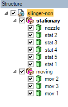
Under each sub-component, the bodies are shared. This sharing is indicated as such by the red line in the component icon. Note however, that the top component's icon does not have any such line. When a line appears in the icon at that level, the setup is incorrect and the Generate Surface Mesh task cannot be completed.