


In order to create a pure (hexagonal) mesh for complicated geometric configurations, you might at times be forced to manually de-construct, or slice, the geometry into separate bodies. A multi-zonal meshing approach ("multizone"), however, can let you create a purely hexagonal mesh throughout all regions of a geometry, automatically deconstructing the geometry into separate bodies. See Understanding Multizone Meshing for more information and details about using multizone meshing.
Use the Add Multizone Controls task in your workflow to set up your own multi-zonal-based controls for the specific regions in your geometric model.
For the Multizone Controls and Sizing for option, select either Regions and Edges so that the multizone controls are generated based on region or edge selection. You can also choose Body Labels for imported CAD geometries that include body labels (and if you have set the Use Body Labels field to Yes in the Import Geometry task, see Importing Geometries).
Note: Edges can be defined in either of the following:
In the CAD model, such that the imported geometry should contain one or more named edges (for example, an ANSYS SpaceClaim Design Modeler CAD geometry with one or more edges explicitly using named selections).
Using either the Extracted Edges field or the Split Cylinders field in the Manage Zones task (see Managing Zones). Note that this option is not available when Separate Zone By is set to face in the Import Geometry task (see Importing Geometries).
Before assigning any edge zone-based multizone controls, you need to first define at least one region-based multizone control.
In addition, since selecting the correct face zones is necessary for proper extraction, if you select multiple zones that share at least one edge, you are prompted to select a minimal set of edges in order to avoid the improper extraction at the location of the shared edges (particularly at T-connections).
When Body Labels is selected for the multizone control, body label names are also listed in the selection list.
For region-based multizone controls, perform the following steps:
Specify the Name for the control, or keep the default value.
Select a choice for the Mesh Method field, or keep the default value. Choices include:
Standard technique.
Thin volume technique (for only a single layer).
Both of these methods support the same region input (fixed sizing or size control functions, etc.)
Select a choice for the Fill With field, or keep the default value. Choices include
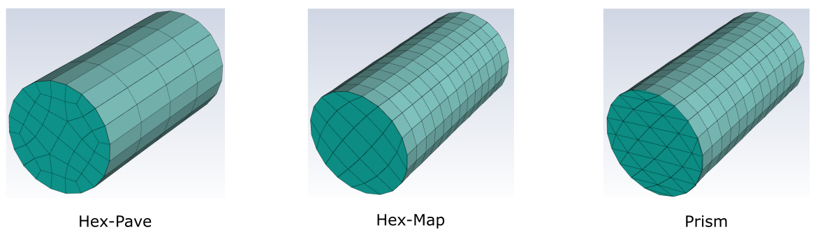
Hex-Pave: fills the selected region(s) with hexahedra elements. All connected regions must use the same volume fill type. If they are set differently, the region fill types will be automatically set to use this fill type.
Hex-Map: fills the selected region(s) with hexahedra elements.
Prism: fills the selected region(s) with prism elements
Mixed: fills the selected region(s) with hexahedra elements in addition to some prism elements.
Note that Hex-Pave can be mixed with Hex-Map within connected regions.
Select a choice for the Use Fixed Sweep Size? field, or keep the default value of no where a variable sweep size (based on size functions) is applied to the multizone mesh. Setting the Use Fixed Sweep Size? field to yes allows you to specify a fixed value for the multizone's sweep size using the Max Sweep Size field.
Note: Any connected multizone control-enabled regions must use the same setting for the Use Fixed Sweep Size? field
Select a region to apply the multizone mesh controls.
Make a Source-Target Selection using the corresponding list (of either Labels or Zones). This allows you to choose your sources and targets manually for the multizone meshing. You can also provide the ability to select all source-target zones that are parallel to a global plane by choosing Zones parallel to XY plane, Zones parallel to XZ plane, or Zones parallel to YZ plane.
When selecting Zones, and when your desired zones are aligned with the global x,y, or z plane, use the Select Parallel Zones checkbox to automatically select all parallel zones in the selected region(s).
Note: You can manually select the regions or source-target selection within the corresponding list, or you can select them using the graphics window by first clicking the
 button, then selecting the regions or surfaces
in the graphics window which automatically selects
the corresponding regions/surfaces in the list.
After clicking the button, the button will become highlighted
(
button, then selecting the regions or surfaces
in the graphics window which automatically selects
the corresponding regions/surfaces in the list.
After clicking the button, the button will become highlighted
( ), indicating that graphical selection is
enabled. Note that if multiple regions/surfaces
have been selected, only the last region/surface
selected in the list can be de-selected using the
graphics window. Additionally, when the
Select Parallel Zones option
is enabled and multiple edges have been selected,
graphical de-selection is not supported.
), indicating that graphical selection is
enabled. Note that if multiple regions/surfaces
have been selected, only the last region/surface
selected in the list can be de-selected using the
graphics window. Additionally, when the
Select Parallel Zones option
is enabled and multiple edges have been selected,
graphical de-selection is not supported.When manually selecting items in the list, you can use the Filter Text option in the drop-down to provide text and/or regular expressions in filtering the list (for example, using *, ?, and []). You can also choose the Use Wildcard option in the drop-down to provide wildcard expressions in filtering the lists. When you use either
?or*in your expression, the matching list item(s) are automatically selected in the list. Use^,|, and&in your expression to indicate boolean operations for NOT, OR, and AND, respectively. See Filtering Lists and Using Wildcards for more information.
For edge-based multizone controls, perform the following steps:
Specify the Name for the control, or keep the default value.
For the Assign Size Using field, indicate whether you want to assign the edge size control based on Interval, Size (the default), or Smallest Height.
Depending on your selection, you will need to provide a value for the Number of Intervals, the minimum Size, or the Smallest Height for the edge-based multizone control, accordingly.
Select a Growth Pattern, where the choices provide a visual indication of the pattern of growth for the volume mesh extrusion.
For edge size controls, and when using the variable Growth Patterns, you can also determine how the growth is to be determined using the Assign Growth Using field, where you can choose to provide a Growth Rate or a Bias Factor. The Bias Factor is the ratio of the largest to the smallest segment on the edge.
When your desired edges are aligned with the global x,y, or z plane, use the Select Parallel Edges checkbox to automatically select all parallel edges in the selected region(s).
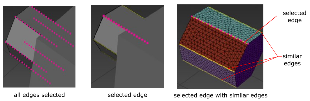
If edge labels are automatically created on all edges, preserving the face/edge topology, you can use the Show edge biasing? field to determine if you want to save time and preview any edge biasing, since when many edges are selected, there can be many nodes and biases that can take additional time.
Select yes, selected (the default in new cases) to limit the preview to only the explicitly selected edges. The selection can be either from the list of edges, or directly from the graphics window. Any remaining edges that are similar to those selected are highlighted in yellow.
Select yes, all (the default for existing models) to have the preview contain all edges.
Select no to not preview any edge biasing.
Note:If you are defining edge-based named selection in your CAD model in order to use edge-based multizone meshing, you must separate the face zones by an angle that results in a face zone boundary along each of the defined edges in the Generate Surface Mesh task (see Generating the Surface Mesh).
If a connected multizone control-enabled region contains both sweep size and edge-based sizing, the sizing that results in the highest cell count will be honored.
In some cases, particularly using edge size controls based on the Interval or the Smallest Height, there will be some differences between the mesh preview and the mesh itself. This is due to Fluent's use of simplified algorithms in meshing mode to ensure optimal performance.
Click Add Multizone Controls to create and add the specified multizone control to your workflow. Your can re-use the task to create as many separate multizone controls as you require.
If you need to make adjustments to any of your settings in this task, click Edit, make your changes and click Update, or click Cancel to cancel your changes.
Essentially, the concept of "multizone meshing" is equivalent to generating a mesh by performing a “sweep” along a particular direction, often involving multiple bodies. The technique requires a number of source and target faces that are normal to the sweep direction and uses them to create hexahedra (or hexahedra-dominant) meshes.
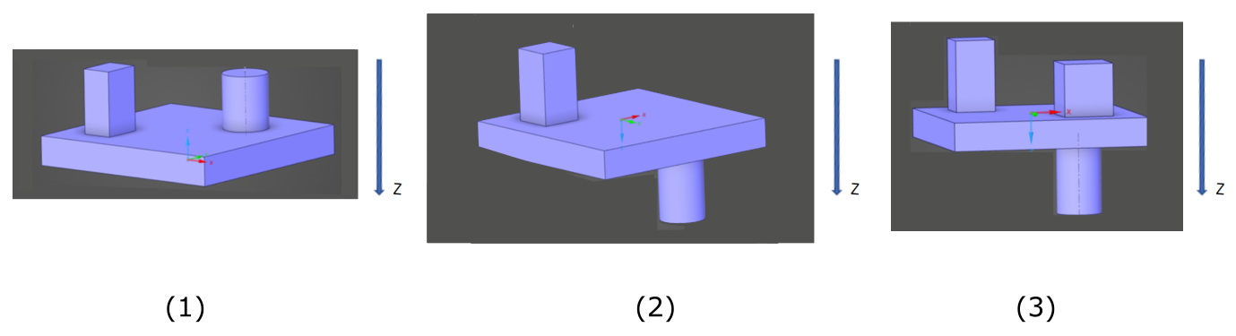
If you examine Figure 3.23: Sample Geometries, the first illustration (1) represents a single body, where the “sweep-able” direction (Z) is from top to bottom. You would need to provide all faces normal to that direction (that is, the top two faces, and both large faces on each side of the block) as the source/ target selections. The multizone technique would also apply even if the geometry represented three connected bodies (using share topology), where, in that case, additional shared faces would need to be added to the source-target selection. Likewise, the multizone technique can also be applied to illustration (2) using essentially the same selections.
Illustration (3) however, represents a scenario where the multizone technique would not be easily applicable. This is due to the fact that the upper right-hand block and the lower right-hand cylinder overlap in the same plane (as you view the model from above or below in the sweep direction). A non-conformal connection between the cylinder and the plate are required for the multizone method to work in this situation.
There are some additional requirements or recommendations that need to be met for a successful and high quality mesh using the multizone technique.
All zones need to be separated by angle. There are two options available to do this:
In the Generate Surface Mesh task, set Separate Out Boundary Zones by Angle? to Yes. The zones would be re-merged back together once you generate the volume mesh.
Insert a Manage Zones task before the Add Multizone Control task, and use the default separation to separate out the bodies that will be meshed for multizone meshing. These bodies will also be merged back together once you generate the volume mesh. Note that this option is not available when Separate Zone By is set to face in the Import Geometry task (see Importing Geometries).
When you are using multizone meshing on very thin plates (for example, thinner than the minimum size), the improve surface mesh operations in the Generate Surface Mesh task can inadvertently damage the geometry. There are two options available to avoid this:
In the Generate Surface Mesh task under Advanced Options, set the Invoke Quality Improve? prompt to No.
If you have regions that are not being meshed using multizone, and for which surface quality improvements are necessary, insert an Improve Surface Mesh task directly after the Add Multizone Control task.
If you experience multizone meshes where the mesh on cylinders appears to be “twisted”, insert a Manage Zones task before the Add Multizone Control task and use the Split Cylinder operation to split the cylinders, which will reduce the twist. Note that this option is not available when Separate Zone By is set to face in the Import Geometry task (see Importing Geometries).
If you are applying multizone meshing to thin plates, the Thin mesh method option may be more stable and faster than the Standard option.
With nonconformal multizone meshing, interface zone types are automatically created on the non-conformal interface boundaries. This can be an issue when adding mesh boundary layers along only walls (that is, when you set the Grow on option to only-walls in the Add Boundary Layer task).
Boundary layers in multizone meshing are not as “flexible” as the boundary layers with unstructured meshes since they do not include stair-stepping and gap factors and local shrinkage is not predictable. When working with boundary layers, try the following strategies:
Start by testing without boundary layers to ensure that it works
Start with uniform boundary layers, as boundary layer shrinkage is easily predictable
If the default boundary layer option (only-walls) proves unsatisfactory, try the all-zones option instead.