


You can define boundary layers along various regions using the Add Boundary Layers task. This task can be added to the workflow as many times as you require. See Prism Meshing Options for Scoped Prisms for more information.
For the Add Boundary Layers? field:
Select yes if you need to specify boundary layers using this task.
Select no if you do not need to account for boundary layers. Click Update and proceed to the next task.
Select yes, using prism control file if you have a prism control file that contains the definition of the boundary layer, and there are no other boundary layer settings already added to this task. You can use the Read Prism Control File field to specify (or browse for) a
.pzmcontrolfile. The corresponding fields in this task will be populated based on the contents of the prism control file.
Note:While you can only read a single boundary layer/prism control file into the task, afterwords, you can add any number of boundary layer controls to the task as required.
Advanced options (such as acute angles, invalid normals, etc.) are not supported if you choose to read a prism control file into this task. In addition, boundary layer controls can be added to the task, however, any conflicts that may occur between controls that are read in from a file and controls that are added to the task are not checked by the system.
Prism control files can also be created in the workflow as part of the Generate the Volume Mesh task (see Generating the Volume Mesh).
Specify a Name for the boundary layer, or use the default value. Note that the default name is dependent on the value of the Offset Method Type.
Choose an Offset Method Type. The offset method that you choose determines how the mesh cells closest to the boundary are generated. See Offset Distances for more information. Choices include:
aspect-ratio: allows you to control the aspect ratio of the boundary layer cells (or prism cells) that are extruded from the base boundary zone. The aspect ratio is defined as the ratio of the prism base length to the prism layer height.
uniform: allows you to generate every new node (child) to be initially the same distance away from its parent node (that is, the corresponding node on the previous layer, from which the direction vector is pointing).
last-ratio: allows you to control the aspect ratio of the boundary layer cells (or prism cells) that are extruded from the base boundary zone.
smooth-transition: allows you to use the local tetrahedral element size to compute each local initial height and total height so that the rate of volume change is smooth. Each triangle that is being inflated will have an initial height that is computed with respect to its area, averaged at the nodes. This means that for a uniform mesh, the initial heights will be roughly the same, while for a varying mesh, the initial heights will vary
The following are additional fields that can be set, depending on the value of the Offset Method Type.
If the Offset Method Type is set to smooth-transition or last-ratio, specify the Transition Ratio. This value determines the ratio of the height of the last layer in the inflation and the first cell in the volume fill.
If the Offset Method Type is set to last-ratio, specify First Height for the height of the first layer of cells in the boundary layer.
If the Offset Method Type is set to aspect-ratio, specify the First Aspect Ratio. You can control the heights of the inflation layers by defining the aspect ratio of the inflations that are extruded from the inflation base. The aspect ratio is defined as the ratio of the local inflation base size to the inflation layer height. The value for the First Aspect Ratio allows you to specify the first aspect ratio to be used.
If the Offset Method Type is not set to last-ratio, provide the Growth Rate. This value determines the relative thickness of adjacent inflation layers. As you move away from the face to which the inflation control is applied, each successive layer is approximately one growth rate factor thicker than the previous one.
Specify the Number of Layers. This value determines the maximum number of boundary layers to be created in the mesh.
For the Add in field, specify what regions you would like to add the boundary layers.
Use the fluid-regions option to add the boundary layer to just the fluid regions.
Use the solid-regions option to add the boundary layer to just the solid regions.
Use the named-regions option to select from a list of available named region(s) in your simulation.
For imported CAD geometries that include body labels (and if you have set the Use Body Labels field to Yes in the Import Geometry task, see Importing Geometries), body label names are also listed alongside named regions in the selection list.
For the Grow on field, specify where you would like to develop the boundary layers.
Use the only-walls option to grow the boundary layer along just wall surfaces.
Use the all-zones option to grow the boundary layer along all surfaces or zones.
Use the solid-fluid-interface option to grow the boundary layer along just interface of the fluid and solid region.
Use the selected-zones option to select from the Zones list of available named zone(s) in your geometry.
Use the selected-labels option to select from the Labels list of available named label(s) in your geometry.
For the selected-zones and selected-labels options, select items in the list, or use the Filter Text option in the drop-down to provide text and/or regular expressions in filtering the list (for example, using *, ?, and []). You can also choose the Use Wildcard option in the drop-down to provide wildcard expressions in filtering the list. When you use either
?or*in your expression, the matching list item(s) are automatically selected in the list. Use^,|, and&in your expression to indicate boolean operations for NOT, OR, and AND, respectively. See Filtering Lists and Using Wildcards for more information.
Click Advanced Options to access additional controls prior to performing this task.
Use the Ignore Boundary Layers at Acute Angles? option to choose whether to automatically ignore boundary layers where there are acute angles.
Note that if there are sharp angles adjacent to other regions with boundary layers, some boundary layer removal may occur in those adjacent regions.
If you indicated yes to the Ignore Boundary Layers at Acute Angles? prompt, you can use the Acute Angle Buffer Layers option to indicate the number of buffer layers that can be placed around ignored boundary layer faces, extending the ignored regions around sharp angles. Increasing the Acute Angle Buffer Layers value increases the number of faces for which the boundary layer will be ignored at acute angles.
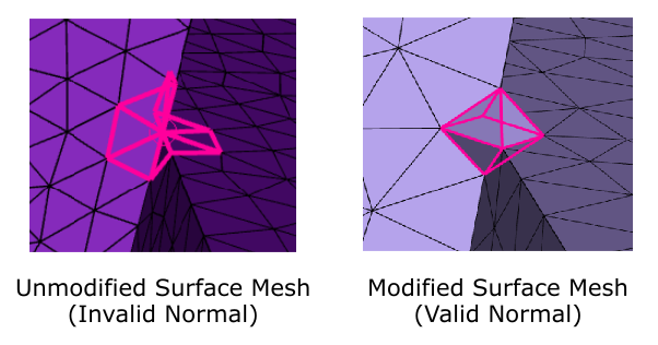
Use the Modify Surface Mesh at Invalid Normals? option to choose whether to automatically change the surface mesh where invalid normal faces are detected.
Note: This option is not supported when working with non-conformal meshes, that is, when the non-conformal prompt is enabled in the Describe Geometry task (Describing the Geometry).
To grow the boundary layer mesh in the proper direction (away from the boundary), normal vectors (valid) are required at the boundary face nodes of the surface mesh.
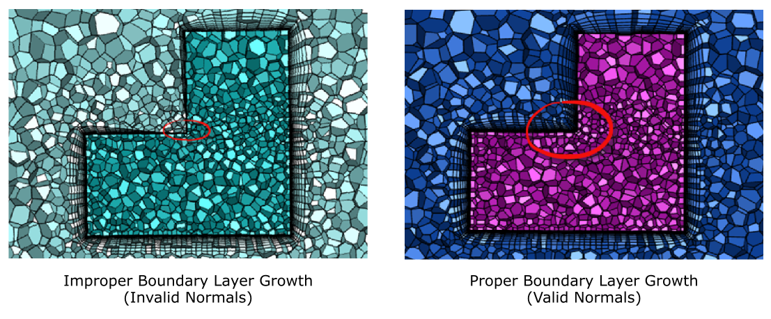
In some cases, the normal vector cannot be determined using the normals of all surrounding face normals (invalid), and the surface mesh must be modified by introducing an octahedral dead region where a normal vector can then be evaluated.
Such dead regions will subsequently be visible in the Update Regions task upon generation of the volume mesh.
Invalid normals are indicated in the graphics window using spheres.

When you specify for the Modify Surface Mesh at Invalid Normals? prompt, the following options are available to you when working with invalid normals:
Use the Sphere Radius Factor at Invalid Normals option to determine the size of the spheres created at the invalid normal location. The spheres have a radius of one half of the average mesh edge length adjacent to the invalid location. The default factor of 0.8 ensures a sphere size that is slightly smaller than that.
Use the Allowed Tangency at Invalid Normals option to control the tangency of the invalid normal faces. An "invalid normal" location with all 90 degree angles has a tangency of 1, so faces are still treated as an invalid normal even if the angle deviates slightly from 90 degrees (resulting in a tangency of 0.98).
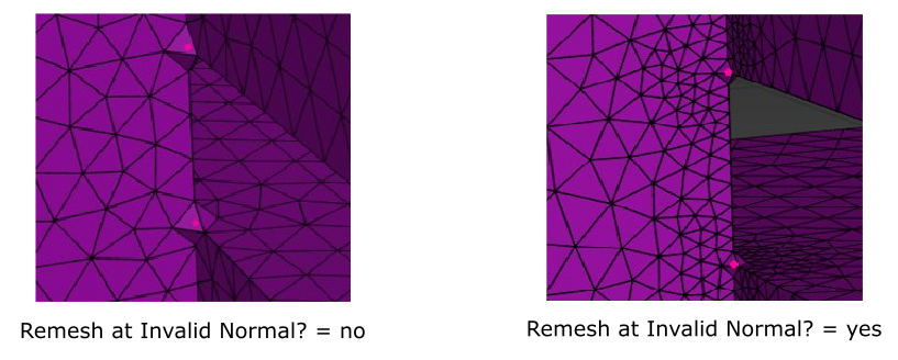
Use the Remesh at Invalid Normals? option to determine whether or not to remesh around the area of the invalid normal(s). When enabled, a local (non-size function-based) remeshing procedure is performed to obtain similar sizes around the sphere with a reasonable transition to the surrounding mesh.
Note: When verbosity is enabled, the x, y, and z locations of each invalid normal are printed in the console
Additional, global boundary layer settings are available in the Generate the Volume Mesh task (Generating the Volume Mesh).
(optional) Use the Draw Regions button to visually display all regions, or just the fluid region(s).
Click Add Boundary Layers to generate the appropriate boundary layers for the imported CAD geometry.
If you need to make adjustments to any of your settings in this task, click Revert and Edit, make your changes and click Update, or click Cancel to cancel your changes.