You can use the Add Thin Volume Meshing Controls task to create a layered mesh within thin structures that can be combined with fill methods for volume mesh generation. Thin volume meshing controls can also be utilized for meshing stacked planar plates as described in Thin Volume Meshing of Stacked Plates. Prior to using this task, note the following assumptions and limitations:
Other than for stacked plates, the structure where thin meshing is applied should be "thin" and have a height/base ratio less than 5.
Boundary layers are not supported within thin volume regions. All thin volume regions will be filtered out from the list of available regions in the Add Boundary Layers task.
The Add Thin Volume Meshing Controls task must be inserted before the Add Boundary Layers task.
Thin volume meshing is not compatible with periodic boundaries.
If you create both a multizone mesh and a thin volume mesh (in different regions), the Non-Conformal Mesh between Multizone and the rest? option will automatically be enabled within the Generate the Multizone Mesh task.
When the Add Thin Volume Meshing Controls task is added, all regions (with or without thin volume mesh controls) will be meshed in serial.
For some configurations, robustness issues may arise which can usually be resolved by using a finer mesh. Additionally, it is recommended that all gaps have a minimum resolution of 1 cell per gap.
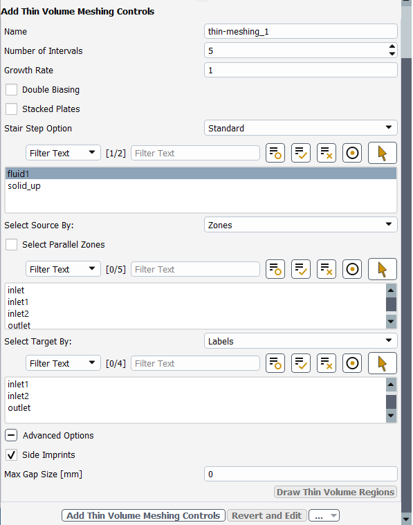
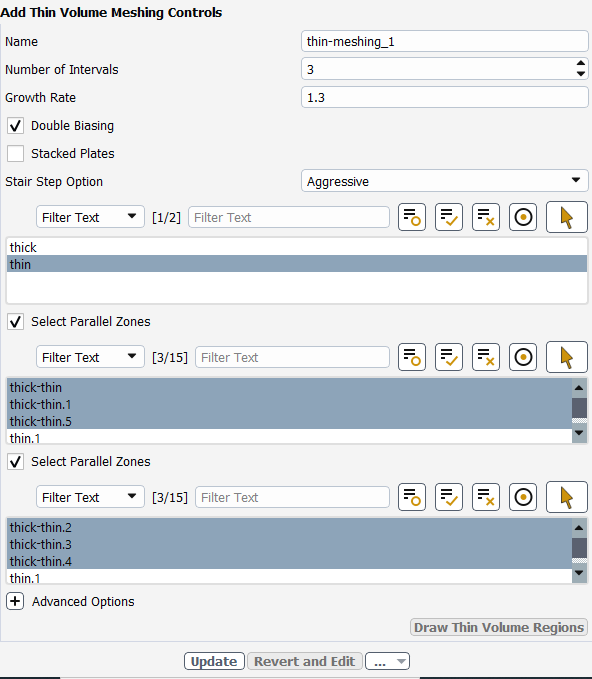
Specify the thin volume mesh parameters:
The Growth Rate defines the expansion rate of the extrusion for each thin volume mesh layer and is set to 1 by default. A growth rate of 1.2 for example will expand each layer of the extrusion by 20 percent of the previous length.
Doubling biasing on edges of the thin volume mesh layers can be invoked by enabling the Double Biasing option. Enabling double biasing will automatically set the Growth Rate to 1.3.
Note: When Double Biasing is disabled, the thin volume mesh can only be graded from the Source to the Target.
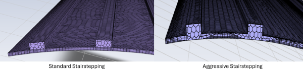
Choose whether to have Standard or Aggressive stairstepping for the Stairstep option.
Select the Region where thin volume meshing is to be applied.
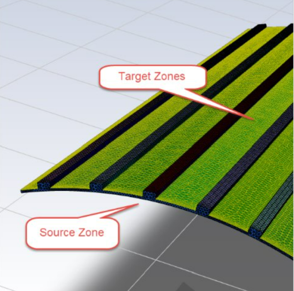
Choose how you want to select the Source and Target, by Labels or by Zones. Note that the thin volume mesh will be created in the region between the selected source and target surfaces. For example, the source and target surfaces for an electromagnetic air-gap model can be visualized in Figure 3.16: Target and Source Zones for Electromagnetic Air-Gap Model below.
Note: You can manually select regions and source/target surfaces within the lists, or you can select them using the graphics window by first clicking the
 button, then selecting the regions/surfaces in
the graphics window which will automatically update
the selected regions/surfaces in the list. Note that
after clicking the button, the button will become highlighted
(
button, then selecting the regions/surfaces in
the graphics window which will automatically update
the selected regions/surfaces in the list. Note that
after clicking the button, the button will become highlighted
( ), indicating that graphical selection is
enabled.
), indicating that graphical selection is
enabled.When manually selecting items in this lists, you can use the Filter Text option in the drop-down to provide text and/or regular expressions in filtering the list (for example, using *, ?, and []). You can also choose the Use Wildcard option in the drop-down to provide wildcard expressions in filtering the lists. When you use either
?or*in your expression, the matching list item(s) are automatically selected in the list. Use^,|, and&in your expression to indicate boolean operations for NOT, OR, and AND, respectively. See Filtering Lists and Using Wildcards for more information.In the above model, a series of non-thin structures are placed along the top surface of the thin air-gap, whereas the bottom surface of the air-gap is smooth throughout. For this example, and for most cases, the smooth (bottom) surface of the thin structure should be selected as the Source zone. For the Target zone(s), the surface(s) attached to any non-thin structures should be selected.
Note:
The surface mesh size on source and target faces should be between 1 and 2 times the overall thin-region thickness.
If the thin volume region is non-conformally connected to another volumetric region, the source and target region can only be selected by zone.
Click Advanced Options to access additional controls prior to performing this task.
Side Imprints are enabled by default which specifies the mesher to project the outer nodes of the thin volume mesh onto adjacent boundary face zones. This ensures that geometric details of the thin volume are accurately captured at the boundary.
The maximum gap distance (Max Gap Size) between thin mesh layers is computed automatically and should not be changed for most cases.
Click the Add Thin Volume Meshing Controls button to save the changes.
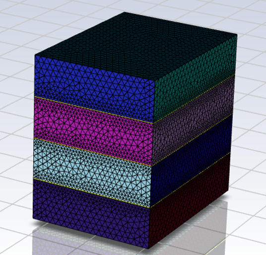
If you have multiple zones in parallel that you want to select for thin meshing, you can enable the Select Parallel Zones option. In Figure 3.17: Stack of Thin and Thick Plates a stack of plates is shown which consists of both thick and thin plates.
In this example, the Select Parallel Zones option can be utilized to create a thin volume mesh for all thin plates within the stack, which are shown in Figure 3.18: Thin Plates.
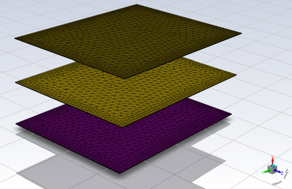
To mesh the thin plates, the thin region is first selected, then the Select Parallel Zones option is enabled for the Source. For the source surfaces, the top surface (facing the positive x-axis) of one of the three plates is selected, which will automatically select the top surface of all three thin plates.
After selecting the source surfaces, the Target surfaces are enabled by following a similar procedure. First the Select Parallel Zones option is enabled, then the bottom surface (facing the negative x-axis) of one of the three plates is selected, which will automatically select the bottom surface of all three thin plates as the target.
For models consisting of stacked planar plates, you have the ability to select all source-target zones that are aligned with the global x-y-z plane by enabling the Stacked Plates option. Note that for thin meshing of stacked plates, only the region(s) and the source face(s) are selected which will automatically specify the source-target zones.
When stacked plates is enabled, thin volume meshing controls can be defined as follows:
Specify the sizing of the mesh layers to be based on Intervals or based on the Size of the plates using the Assign Size Using option.
When Intervals is selected as the Assign Size Using option, specify the number of mesh layers to be created within the thin volume mesh for Number of Intervals.
When Size is selected for the Assign Size Using option, specify the Minimum Number of Intervals desired for the thin mesh and enter the Size of each layer.
Select the stacked plates region(s) where the thin volume mesh will be created.
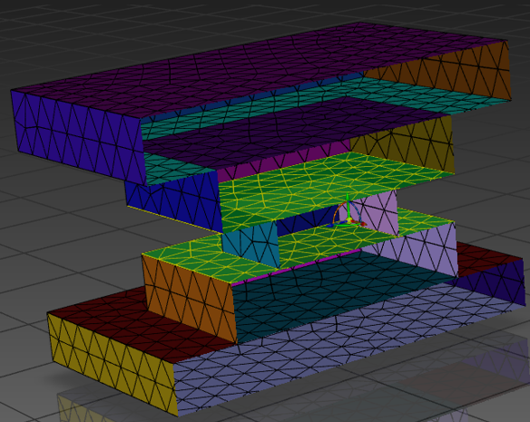
When selecting the source-target zones, you must find the key source face(s) on regions that are imprinted into all selected regions. In general, the key source face will be the plane(s) located within the center of the stack. Figure 3.20: Key Source Faces below shows the 4 key source faces for a stacked plates model.
In the above figure, there are 4 possible key source faces enabled for demonstration purposes. However, only one of the 4 key source faces needs to be specified in order to properly define the source-target zones.
After selecting the key source face for your case, it's recommended to click the button to ensure that the key source selection will properly select the desired source-target zones.
Under Advanced Options:
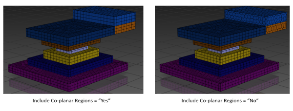
You can use the Include Co-Planar Regions on All Levels option to specify whether or not adjacent stacked plate(s) (as shown in Figure 3.21: Stacked Plates with Co-planar) are included in the thin mesh. This option is set to Yes by default.