


The following variables will be available on all boundary wall regions.
Table 49.2: Variables On Boundary Wall Regions
|
Display Name / Internal Name |
Transfer Direction |
Quantity Type |
|---|---|---|
|
force / |
Output |
Force |
|
displacement / |
Input |
Length |
|
temperature / |
Input and Output |
Temperature |
|
heat rate / |
Input |
Heat Rate |
|
heat flow / |
Input and Output |
Heat Rate |
|
heat transfer coefficient /
|
Input and Output |
Heat Transfer Coefficient |
|
near wall temperature /
|
Output |
Temperature |
The following variables will be available on all cell zone regions.
Table 49.3: Variables On Cell Zone Regions
|
Display Name / Internal Name |
Transfer Direction |
Quantity Type |
|---|---|---|
|
heat rate / |
Input |
Heat Rate |
|
temperature / |
Input and Output |
Temperature |
|
Lorentz force / |
Input |
Force |
|
electrical conductivity /
|
Output |
Electrical conductivity |
The following variables will be available on all porous jump boundaries.
Table 49.4: Variables On Porous Jump Boundary
|
Display Name / Internal Name |
Transfer Direction |
Quantity Type |
|---|---|---|
|
force / |
Output |
Force |
|
displacement / |
Input |
Length |
*Represents the force vector  (
( ,
,  ,
,  ) and the displacements vector
  (
( ,
,  ,
,  ) respectively.
The force vector sent from each wall boundary in Fluent to System Coupling is given by:
 | (49–1) |
where
 is the gauge pressure in Fluent.
 is the pressure rise due to Floating Operating Pressure
if enabled (for details, see Floating Operating Pressure).
is the pressure rise due to Floating Operating Pressure
if enabled (for details, see Floating Operating Pressure). is the Reference Pressure, which differs from the
Operating Pressure (for details, see Reference Values). If the Reference Pressure is set to
zero, then gauge pressure forces will be sent to System Coupling. If it is set to the negative of the
operating pressure, then absolute pressure forces will be sent to System Coupling.
is the Reference Pressure, which differs from the
Operating Pressure (for details, see Reference Values). If the Reference Pressure is set to
zero, then gauge pressure forces will be sent to System Coupling. If it is set to the negative of the
operating pressure, then absolute pressure forces will be sent to System Coupling. is the face area vector.
 is the force vector due to viscous forces.
 is the force vector due to particle forces.
Note: If buoyancy is active, the hydrostatic pressure force due to a nonzero operating density is excluded from the force calculation. To include this contribution, the operating density must be set to 0.
For more information on force calculations, see Computing Forces, Moments, and the Center of Pressure in the Fluent Theory Guide.
When a porous jump boundary is selected as a source region for a System Coupling analysis, the forces transferred from this porous jump boundary are calculated differently depending on if the porous jump is between fluid regions, or between a fluid region and a porous zone.
When the porous jump separates two fluid zones, or forms an interior region in a fluid zone:
The force transferred to System Coupling is the net force across the jump. The thickness and coefficient parameters defined for the porous jump are used to calculate the pressure drop across the jump. This pressure drop is converted to a force vector that is transferred to System Coupling. This force does not include any viscous forces.
When the porous jump separates a porous zone and a fluid zone:
This case will occur if the upstream or downstream fluid-porous interface is changed to a porous jump. The porous jump is used to allow a connection between the upstream and downstream porous zone interface and System Coupling, since the porous zone interface regions cannot connect directly to System Coupling.
The face pressure on the porous jump is converted to a force vector and transferred to System Coupling. A positive face pressure will produce a force vector that always points into the porous zone. The force calculated does not include any viscous forces.
It is best to assign zero-thickness to the porous jump so that there is no pressure drop across the jump. Note that volumetric forces in the porous zone are not passed to System Coupling. This case is intended to model thin porous zones where the deformation of the zone can be approximated by considering only the fluid pressure on the upstream and downstream porous interfaces.
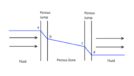
If a nonzero thickness is assigned to a porous jump that is adjacent to a porous zone, then there will be a pressure drop across the porous jump. The force transferred to system coupling is calculated using the face pressure on the upstream side of the porous jump, before the pressure drop across the jump has been applied. See the image below.
Force transferred on the upstream side of the porous zone (a) will be consistent with the upstream fluid pressure (a).
Force transferred on the downstream side of the porous zone (c) will be inconsistent with the downstream fluid pressure (d). On the downstream side of the porous zone, the force transferred to system coupling is consistent with the exit pressure from the porous zone, before the pressure drop across the porous jump has been applied. The downstream fluid pressure is calculated after the pressure drop is applied.
For information about the porous jump boundary condition, see Porous Jump Boundary Conditions.
The following applies in a coupled analysis where displacement is received by Fluent.
The displacement data received by Fluent represents the incremental displacement for the current time step (the incremental displacement since the end of the previous time step).
The displacement variable is only available on walls that have the System Coupling moving and deforming mesh (MDM) option selected, and that qualify as valid coupling regions.
In a general coupled analysis, when Fluent solves before or simultaneously to the solver sending the displacement (such as Mechanical), then during the first coupling iteration of each coupling step the displacement received is 0 [m].
When transferring data to or from a wall boundary in a sliding mesh zone, you must ensure that the coupled participant (such as Mechanical) does not rotate its mesh. One way to do this in Mechanical is to use a Rotational Velocity.
For more information about the Rotational Velocity boundary condition, see Rotational Velocity in the Mechanical User's Guide. For information about sliding meshes in Fluent, see Using Sliding Meshes.
Force transferred from a Fluent wall boundary in a System Coupling analysis is the gauge pressure minus the specified Reference Pressure. You can change the force transferred by changing the Reference Pressure value. The following example of a pressurized sub-sea pipe is a demonstration of how to transfer the absolute pressure in a System Coupling analysis by changing the Reference Pressure.
Consider flow in a pressurized sub-sea pipe. The pipe is pressurized to 110 bar absolute and the exterior water pressure is 100 bar. The exterior sea water is not modeled. The internal surface of the pipe forms an FSI interface to a Mechanical model of the pipe.
In Fluent the Operating Pressure would typically be set to 110 bar. By default the forces passed to System Coupling would only include the local pressure changes relative to 110 bar, which clearly does not represent the real physics. To include the absolute pressure in the forces sent to System Coupling, the Reference Pressure in Fluent should be set to -110 bar. The Mechanical model would then need a pressure of 100 bar applied to the exterior surfaces of the pipe.
Although this approach is valid, it is not ideal because the correct structural solution is only obtained if 100 bar of the interior pressure cancels out with the 100 bar exterior pressure. Relying on two large forces to exactly cancel out is prone to discretization (mesh resolution) errors. Minimizing the forces sent across the FSI interface is also good practice. Therefore the best approach is to use an Operating Pressure of 110 bar and a Reference Pressure of -10 bar in Fluent. The forces Fluent sends to System Coupling are then based on the gauge pressure minus -10 bar, that is, the gauge pressure plus 10 bar. This accounts for the pressure difference between the interior and exterior of the pipe, so there is no need to apply an external pressure in Mechanical. We are no longer relying on two large forces cancelling out and we have minimized the forces sent across the FSI interface.