


The total force component along the specified force vector  on a wall zone is computed by summing the dot product
of the pressure and viscous forces on each face with the specified
force vector. The terms in this summation represent the pressure and
viscous force components in the direction of the vector
on a wall zone is computed by summing the dot product
of the pressure and viscous forces on each face with the specified
force vector. The terms in this summation represent the pressure and
viscous force components in the direction of the vector  :
:
 | (25–3) |
|
where | |
|
| |
|
| |
|
|


In addition to the actual pressure, viscous, and total forces,
the associated force coefficients are also computed for each of the
selected wall zones, using the reference values (as described in Reference Values in
the User's Guide). The force coefficient is defined as force divided by  , where
  ,
,  , and
, and  are the density, velocity, and
area. Finally, the net values of the pressure, viscous, and total
forces and coefficients for all of the selected wall zones are also
computed.
are the density, velocity, and
area. Finally, the net values of the pressure, viscous, and total
forces and coefficients for all of the selected wall zones are also
computed.
The total moment vector about a specified center  is computed by summing the
cross products of the pressure and viscous force vectors for each
face with the moment vector
is computed by summing the
cross products of the pressure and viscous force vectors for each
face with the moment vector  , which is the vector
from the specified moment center
, which is the vector
from the specified moment center  to the force origin
  (see Figure 25.1: Moment About a Specified Moment Center). The terms in this summation
represent the pressure and viscous moment vectors:
(see Figure 25.1: Moment About a Specified Moment Center). The terms in this summation
represent the pressure and viscous moment vectors:
 | (25–4) |
|
where | |
|
| |
|
| |
|
| |
|
| |
|
|


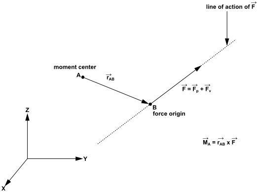
Direction of the total moment vector follows the right hand rule for cross products.
Along with the actual components of the pressure, viscous, and
total moments, the moment coefficients are computed for each of the
selected wall zones, using the reference values (as described in
Reference Values in the User's Guide). The moment coefficient is defined as the moment divided by  , where
  ,
,  ,
,  , and
, and  are the density, velocity, area,
and length. The coefficient values for the individual wall zones are
also summed to yield the net values of the pressure, viscous, and
total moments and coefficients for all of the selected wall zones.
are the density, velocity, area,
and length. The coefficient values for the individual wall zones are
also summed to yield the net values of the pressure, viscous, and
total moments and coefficients for all of the selected wall zones.
Furthermore, the moments along a specified axis are computed. These moments, also known as torques, are defined as the dot product of a unit vector in the direction of the specified axis and the individual and net values of the pressure, viscous, and total moments and coefficients.
To reduce round-off error, a reference pressure is used to normalize the cell pressure for computation of the pressure force. For example, the net pressure force vector, acting on a wall zone, is computed as the vector sum of the individual force vectors for each cell face:
 | (25–5) |
 | (25–6) |
where  is the number of faces,
  is the area of the face, and
  is the unit normal to the face.
Note: For a multiphase flow, the phase-level forces, such as the pressure force
 and viscous force
  , are multiplied by the volume fraction. The mixture-level
forces and moments are the sums of the phase-level forces and moments,
respectively. For example, the pressure force for a given phase is calculated
as:
, are multiplied by the volume fraction. The mixture-level
forces and moments are the sums of the phase-level forces and moments,
respectively. For example, the pressure force for a given phase is calculated
as:
 | (25–7) |
and the pressure force at the mixture level is calculated as:
 | (25–8) |
where  is the number of phases, and
  is the volume fraction.
For a 2D shape, the resulting force due to pressure and viscous stresses is applied along a line (parallel to the resulting force). The center of pressure is the intersecting point of this line with a user-specified reference line (for example, the chord line is generally selected for a 2D airfoil). The resultant moment about this point is then zero.
For a general body in 3D, the pressure and viscous wall stress distribution can be represented by a force (and its application axis) and a moment about a moment center. In general, the problem of finding the translation of the application axis that zeroes the moment does not have a solution. For certain symmetric geometries (for example a non spinning missile), however, this solution exists. In such cases, the center of pressure is usually defined as the intersection of the application axis of the resulting force with a user-specified reference plane.
Ansys Fluent calculates the center of pressure as follows. For a generic moment center and axes, the resultant moment is expressed as
 | (25–9) |
Important: The forces and moments referenced in Equation 25–9 for computing the moment center and axis are only pressure forces and moments and they do not include viscous forces.
In 3D, zeroing two of these equations and using the equation of the user-specified (constraining) reference plane, the intersection point between the application axis and the specified reference plane can be obtained. In 2D, only the last equation in Equation 25–9 is used in combination with the user-specified reference line to calculate the center of pressure.