


For additional information, see the following sections:
You may want to include the effects of the wall roughness on selected wall boundaries as part of your turbulent simulation. In such cases, you can specify the roughness parameters (roughness height and roughness constant) in the dialog boxes of the corresponding wall boundaries (see Wall Roughness Effects in Turbulent Wall-Bounded Flows).
Note: Rough walls cannot be used together with the following model combinations:
an
 -equation model with enhanced wall treatment or the
Menter-Lechner near-wall treatment
-equation model with enhanced wall treatment or the
Menter-Lechner near-wall treatmentNote that the following are the relevant
 -equation models:
 all of the
 -
- models (that is, standard, RNG, and
realizable)
models (that is, standard, RNG, and
realizable)the Reynolds stress model with the Linear Pressure-Strain model selected
the detached eddy simulation (DES) model with the Realizable k-epsilon option selected
the Reynolds stress model with the Stress-Omega or Stress-BSL model selected
the transition
 -
- -
- model
model the large eddy simulation (LES) model
When you are modeling turbulent flows in Ansys Fluent using the Spalart-Allmaras
model, you must provide the boundary conditions for  in addition to other mean solution variables. The boundary
conditions for
in addition to other mean solution variables. The boundary
conditions for  at the walls are internally taken care of by Ansys Fluent, which
obviates the need for your inputs. The boundary condition input for
at the walls are internally taken care of by Ansys Fluent, which
obviates the need for your inputs. The boundary condition input for  , which you must enter in Ansys Fluent, is the one at inlet boundaries
(for example, velocity inlets, pressure inlets). In many situations, it is important
to specify correct or realistic boundary conditions at the inlets, because the inlet
turbulence can significantly affect the downstream flow.
, which you must enter in Ansys Fluent, is the one at inlet boundaries
(for example, velocity inlets, pressure inlets). In many situations, it is important
to specify correct or realistic boundary conditions at the inlets, because the inlet
turbulence can significantly affect the downstream flow.
When you are modeling turbulent flows in Ansys Fluent using one of the  -
- models or one of the
  -
- models, you must provide the boundary conditions for
 and
and  (or
(or  and
and  ) in addition to other mean solution variables. The boundary
conditions for
) in addition to other mean solution variables. The boundary
conditions for  and
and  (or
(or  and
and  ) at the walls are internally taken care of by Ansys Fluent, which
obviates the need for your inputs. The boundary condition inputs for
) at the walls are internally taken care of by Ansys Fluent, which
obviates the need for your inputs. The boundary condition inputs for  and
and  (or
(or  and
and  ), which you must enter in Ansys Fluent, are the ones at inlet
boundaries (for example, velocity inlets, pressure inlets). In many situations, it
is important to specify correct or realistic boundary conditions at the inlets,
because the inlet turbulence can significantly affect the downstream flow.
), which you must enter in Ansys Fluent, are the ones at inlet
boundaries (for example, velocity inlets, pressure inlets). In many situations, it
is important to specify correct or realistic boundary conditions at the inlets,
because the inlet turbulence can significantly affect the downstream flow.
See Determining Turbulence Parameters for details about specifying the boundary
conditions for  and
and  (or
(or  and
and  ) at the inlets.
Additionally, you can control whether or not to set the turbulent viscosity to
zero within a laminar zone. If the fluid zone in question is laminar, the text
command define/
boundary-conditions/fluid will contain an option called
Set Turbulent Viscosity to zero within laminar zone?.
By setting this option to yes, Ansys Fluent will set both the
production term in the turbulence transport equation and  to zero. The same defaults are applied when the Laminar
Zone option is enabled in a Fluid cell zone
condition dialog box. See Specifying a Laminar Zone for details
about laminar zones.
to zero. The same defaults are applied when the Laminar
Zone option is enabled in a Fluid cell zone
condition dialog box. See Specifying a Laminar Zone for details
about laminar zones.
Important: Note that the laminar zone feature is also available for the Spalart-Allmaras and Reynolds stress models.
The specification of turbulent boundary conditions for the RSM is the same as for the other turbulence models for all boundaries except at boundaries where flow enters the domain. Additional input methods are available for these boundaries and are described here.
When you choose to use the RSM, the default inlet boundary condition
inputs required are identical to those required when the  -
- model is active. You
can input the turbulence quantities using any of the turbulence specification
methods described in Determining Turbulence Parameters. Ansys Fluent then
uses the specified turbulence quantities to derive the Reynolds stresses
at the inlet from the assumption of isotropy of turbulence:
model is active. You
can input the turbulence quantities using any of the turbulence specification
methods described in Determining Turbulence Parameters. Ansys Fluent then
uses the specified turbulence quantities to derive the Reynolds stresses
at the inlet from the assumption of isotropy of turbulence:
 | (15–4) |
 | (15–5) |
where  is the normal Reynolds stress component in each
direction. The boundary condition for
is the normal Reynolds stress component in each
direction. The boundary condition for  is determined in the same
manner as for the
is determined in the same
manner as for the  -
- turbulence models (see Determining Turbulence Parameters). To use this method, you will select K or Turbulent Intensity as the Reynolds-Stress
Specification Method in the appropriate boundary condition
dialog box.
turbulence models (see Determining Turbulence Parameters). To use this method, you will select K or Turbulent Intensity as the Reynolds-Stress
Specification Method in the appropriate boundary condition
dialog box.
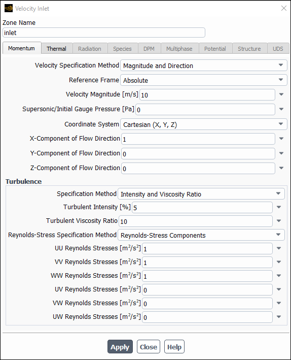
Alternately, you can directly specify the Reynolds stresses by selecting the Reynolds-Stress Components as the Reynolds-Stress Specification Method in the boundary condition dialog box. When this option is selected, you should input the Reynolds stresses directly.
You can set the Reynolds stresses by using constant values, profile functions of coordinates (see Profiles), or user-defined functions (in the Fluent Customization Manual).
In Scale Resolving Simulations, it is possible to specify unsteady fluctuating velocity at velocity and pressure inlets to generate realistic turbulent content. The specified velocity and turbulent parameters are used to generate the fluctuations. For details, see Inlet Boundary Conditions for Scale Resolving Simulations in the Fluent Theory Guide.