For information regarding the theory behind the crevice model, see Crevice Model in the Theory Guide. Using the crevice models in Ansys Fluent are described in the following sections:
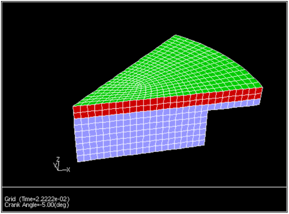
An optical experimental engine [37] is used below to show a working example of how to use the crevice model as it is implemented in Ansys Fluent. The mesh at ten crank angle degrees before top center is shown in Figure 21.7: Experimental Engine Mesh.
The following example shows the necessary steps to enable the crevice model for a typical in-cylinder flow.
From the > prompt, enter the
define/modelsmenu by using the following text command:define→modelsEnable the crevice model, as follows:
/define/models
crevice-model?Enable crevice model? [no]yesEnter the ring pack geometry:
/define/models
crevice-model-controlsCylinder bore (m) [0.1]0.1397Piston to bore clearance (m) [3.0e-5]5.08e-05Piston crevice temperature (K) [400]433Piston sector angle (deg) [360]45Ring discharge coefficient [0.8]0.7Pressure in crankcase (exit pressure) (Pa) [101325] Write out crevice data to a file? [no]yesoutput file name ["crev.out"] Available wall threads are: (wall.1 wall wall-8) Leaking wall []wall.1Shared boundary []wall-8Selected boundary threads : (wall.1 wall-8) Use these zones? [yes]yesSolve crevice model ? [no]yesNumber of rings [3] Width of ring number 0 is: [0.00375] Thickness of ring number 0 is: [0.0015] Spacing of ring number 0 is: [0.008] Land Length for ring number 0 is: [0.00391] Top Gap of ring number 0 is: [6e-05] Middle Gap of ring number 0 is: [4e-05] Bottom Gap of ring number 0 is: [6e-05] Width of ring number 1 is: [0.00375] Thickness of ring number 1 is: [0.0015] Spacing of ring number 1 is: [0.008] Land Length for ring number 1 is: [0.00391] Top Gap of ring number 1 is: [6e-05] Middle Gap of ring number 1 is: [4e-05] Bottom Gap of ring number 1 is: [6e-05] Width of ring number 2 is: [0.00375] Thickness of ring number 2 is: [0.0015] Spacing of ring number 2 is: [0.00391] Land Length for ring number 2 is: [0.00391] Top Gap of ring number 2 is: [6e-05] Middle Gap of ring number 2 is: [4e-05] Bottom Gap of ring number 2 is: [6e-05] Initial conditions in ring pack Pressure 1 is: [4600623.5] Pressure 2 is: [4173522.5] Pressure 3 is: [3689110.5] Pressure 4 is: [3130620] Pressure 5 is: [2214841.8]A fast way to set up multiple rings in the ring pack is to specify only one ring and enter the geometry. Once the ring geometry is entered, invoke the
crevice-model-controlsmenu a second time and specify the number of rings desired. When the number of rings changes, the geometry from the first ring is copied to all subsequent rings. Default values can be taken for the rest of the way through the menu structure.A summary of the crevice model is printed out by entering the
(crevice-summary)command at the command prompt:>(crevice-summary) crevice/n-rings : 3 crevice/ring-width : (0.00375 0.00375 0.00375) crevice/ring-thickness : (0.0015 0.0015 0.0015) crevice/ring-mass : (0.00375 0.00375 0.00375) crevice/ring-spacing : (0.008 0.008 0.00391) crevice/land-length : (0.00391 0.00391 0.00391) crevice/top-ring-gap : (6e-05 6e-05 6e-05) crevice/mid-ring-gap : (4e-05 4e-05 4e-05) crevice/bot-ring-gap : (6e-05 6e-05 6e-05) crevice/piston-temperature : 433 crevice/sector-angle : 45 crevice/mid-gap-cd : 0.7 crevice/exit-pressure : 101325 crevice/threads : (5 6) names of crevice/threads : (wall.1 wall-8) crevice/unit-roundoff : 5.9604645e-08 crevice/piston-bore-clearance : 5.08e-05 crevice/write? : #t crevice/output-file : crev.out crevice/solve? : #t crevice/enabled? : #t crevice/pressures : (4600623.5 4173522.5 3689110.5 3130620 2214841)
The under-relaxation factor for the crevice model source terms can be found in the Solution Controls task page. The default value for Crevice Model Sources is 0.8, which has been found to work well for motored engine simulations. Once the crevice model is enabled, the solution proceeds normally.
![]() Solution →
Solution → ![]() Controls
Controls
![]() Solution →
Solution → ![]() Initialization
Initialization
![]() Solution →
Solution → ![]() Run Calculation
Run Calculation
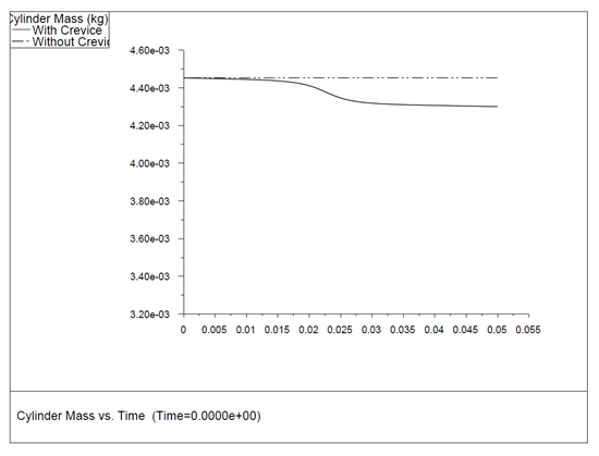
A plot of cylinder mass with and without the crevice model during the motored engine simulation is shown in Figure 21.8: Cylinder Mass vs. Crank Angle. The rate of mass loss from the crevice is proportional to the pressure difference between the cylinder and the crankcase pressure defined in the text interface.
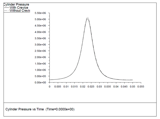
A plot of cylinder pressure with and without the crevice model for the same engine simulation is shown in Figure 21.9: Cylinder Pressure vs. Crank Angle. The effect of the mass loss from the crevice is to lower the peak pressure in proportion to the total mass loss from the cylinder.
The pressure in the top ring land is defined as the cylinder
pressure (that is, the pressure in the cells defining the ring landing).
Intermediate pressures are available at any point during the Ansys Fluent session
through the (crevice-summary) command as
previously shown. If the optional data file output is chosen in the crevice-model-controls, the intermediate pressures in
the defined crevices are printed to the file crev.out at the start of each new time step. The format of the file is as
follows:
 # crank (deg) data-press[0...1...2...3...4...5...6] total_mdot
1.95500e+02 2.16650e+05 1.01325e+05 1.01325e+05 1.01325e+05 1.01325e+05 1.01325e+05 1.01325e+05 0.0
1.96000e+02 2.09945e+05 1.06794e+05 1.81553e+05 1.04111e+05 1.48582e+05 1.02202e+05 1.01325e+05 -1.6
1.96500e+02 2.17787e+05 1.13070e+05 1.88242e+05 1.07960e+05 1.53544e+05 1.03526e+05 1.01325e+05 -1.6
1.97000e+02 2.17434e+05 1.19065e+05 1.88060e+05 1.11705e+05 1.53475e+05 1.04830e+05 1.01325e+05 -1.6
1.97500e+02 2.17652e+05 1.24777e+05 1.88299e+05 1.15286e+05 1.53668e+05 1.06081e+05 1.01325e+05 -1.6
1.98000e+02 2.17937e+05 1.30215e+05 1.88594e+05 1.18711e+05 1.53900e+05 1.07283e+05 1.01325e+05 -1.6
where the first column is the current flow time (or crank angle),
and the next  columns
are the ring pressures (where
columns
are the ring pressures (where  is the number of crevice volumes, or
  ), including the face pressure on the crevice cell, and the defined
pressure at the crevice exit. The final column is the mass flow past
the top ring. This file is currently formatted so that it can be read
into the free Gnuplot plotting package, which
is available at
), including the face pressure on the crevice cell, and the defined
pressure at the crevice exit. The final column is the mass flow past
the top ring. This file is currently formatted so that it can be read
into the free Gnuplot plotting package, which
is available at www.gnuplot.info.
To read the crevice output file into Ansys Fluent as a data file, you will need to put each column of the crevice output file in its own individual file. The first three lines of each column of the data file should be of the following form:
 "Title"
 "X-Label" "Y-Label"
 0 0 0 0
where the title,  -label, and
  -label strings are enclosed by double quotes and
the third line of the file contains four zeros. The lines following
the first three lines of the file are the columns you want to plot.
For example, to plot column 1 versus column 3 of the crevice model
output file in Ansys Fluent, you would enter the following commands
in a Linux terminal:
-label strings are enclosed by double quotes and
the third line of the file contains four zeros. The lines following
the first three lines of the file are the columns you want to plot.
For example, to plot column 1 versus column 3 of the crevice model
output file in Ansys Fluent, you would enter the following commands
in a Linux terminal:
 cat > crev_col_1_3.dat.h5
 "Column 1 vs Column 3"
 "Crank Angle (deg)" "Pressure behind ring 1 (Pa)"
 0 0 0 0
 ctrl-d
where ctrl-d is the end-of-file character
made holding down the Ctrl key and pressing d (Ctrl+d). To append columns 1 and 3 to this file, enter the following:
tail +2 crev.out | awk ’{print $1, $3}’ >> crev_col_1_3.dat.h5
The file crev_col_1_3.dat.h5 can now be read
into Ansys Fluent using the Plot Data Sources Dialog Box. See Creating an XY Plot From Multiple Data Sources (Including Files) for details about creating  -
-  plots. For Windows users, the file
 crev.out can
be imported into Excel for plotting purposes without any modification.
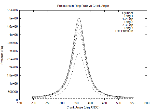
A Gnuplot plot of the pressure in the ring pack crevices for the above engine simulation is shown in Figure 21.10: Crevice Pressures. After an initial transient period where the flows in the network settle down, Figure 21.10: Crevice Pressures shows that the pressure in the ring crevices follows the cylinder pressure in form, though with pressure magnitudes that are controlled by the ring pack geometry.