VM282
VM282
Mode-Superposition Response Analysis of a Piston-Fluid
System
Overview
| Reference: |
Axisa, F., Antunes, J., Modelling Mechanical Systems: Fluid-Structure Interaction, 2006, p. 486 |
| Analysis Type(s): | |
| Element Type(s): | |
| Input Listing: | vm282.dat |
Test Case
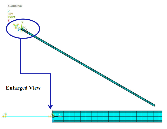
A simple piston-fluid system is modeled using a spring damper element (COMBIN14) for the piston, fluid elements (FLUID30) for the fluid column, and a mass element (MASS21) for the mass of the piston, as shown in Figure 488: Schematic Representation of a Spring-Mass Damper System Coupled to a Compressible Fluid Column in a Tube. The contact between the piston and the fluid column is established using the surface-to-surface contact element (CONTA174).
The piston is driven by a harmonic force F0eiωt along the axial direction. A mode-superposition (MSUP) harmonic analysis is performed to investigate the displacement of the piston and the pressure amplitude at mid-column.
Figure 488: Schematic Representation of a Spring-Mass Damper System Coupled to a Compressible Fluid Column in a Tube
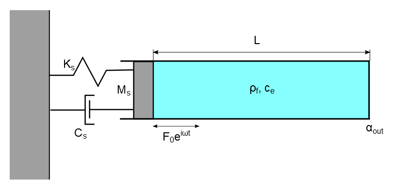
Figure 489: Finite Element Representation of a Spring-Mass Damper System Coupled to a Compressible Fluid Column in a Tube
| Material Properties | Geometric Properties | Loading | |||||||||||||
|---|---|---|---|---|---|---|---|---|---|---|---|---|---|---|---|
|
|
|

[a] The modal damping ratios were obtained in a separate modal analysis using the damped eigensolver.
Analysis Assumptions and Modeling Notes
The piston is modeled as a 1D spring-mass system with one end fixed. The fluid column is modeled as a straight tube of constant cross-sectional area filled with a compressible fluid. The tube is closed at the outlet.
The MPC-based contact pairs are established using CONTA174 elements (KEYOPT(2) = 2) between the piston and the fluid column. The fluid-structure interaction (FSI) condition is defined using the SF,,FSI command at the interface between the piston and the fluid column.
A modal analysis of the piston-fluid system is performed using the unsymmetric eigensolver. The frequencies obtained from this simulation are compared with the analytical solution.
After performing the modal solve, the response of the piston-fluid system is evaluated using a mode-superposition harmonic analysis for a frequency range of excitation between 0-100 Hz. The damping in the piston is considered by specifying modal damping ratios (MDAMP). These results are then compared with the analytical solution.
Results Comparison
| Modal Frequency | Target | Mechanical APDL | Ratio |
|---|---|---|---|
| f1, Hz | 9.916 | 9.877 | 0.996 |
| f2, Hz | 24.583 | 24.305 | 0.989 |
| f3, Hz | 43.729 | 43.526 | 0.995 |
| f4, Hz | 63.895 | 63.760 | 0.998 |
| f5, Hz | 84.395 | 84.292 | 0.999 |
| Target | Mechanical APDL | Ratio | |
|---|---|---|---|
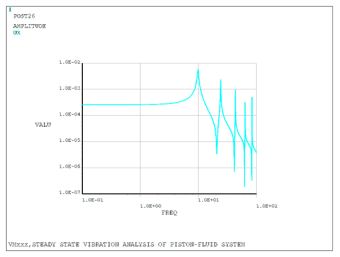
| Piston displacement amplitude at 1.0 Hz, m | 0.00025 | 0.00026 | 1.052 |
| Piston displacement amplitude at f1, m | 0.00576 | 0.00575 | 0.998 |
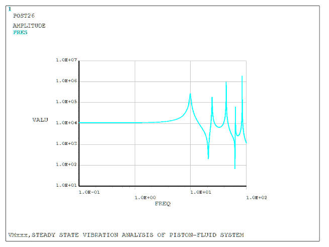
| Fluid pressure amplitude at 1.0 Hz, MPa | 10300.000 | 10881.003 | 1.056 |
| Fluid pressure amplitude at f1, MPa | 264000.000 | 263403.917 | 0.998 |
The nodal solution plot (NSOL) shows the response with respect to the frequency of excitation.