VM283
VM283
Low Reduced Frequency Model for Visco-thermal Fluid with
Thin Structure
Overview
Test Case
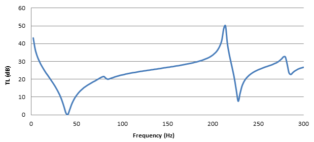
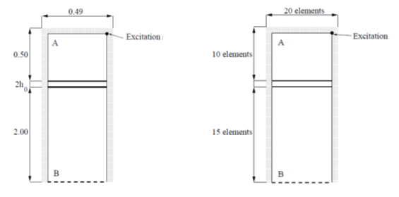
The acoustic transmission loss between two rooms separated by a double-wall aluminum panel is calculated in a frequency range from 10 to 300 Hz. An excitation source in room A generates a pressure field, and the panel transmits a part of the incident energy into room B. All transmitted energy will be absorbed at the impedance boundary at the far end of room B. The walls of room A and B are hard, except for the sides coupled to the double wall panel and the impedance boundary.
| Material Properties | Geometric Properties | |||||||||||||||
|---|---|---|---|---|---|---|---|---|---|---|---|---|---|---|---|---|
|
|
Analysis Assumptions and Modeling Notes
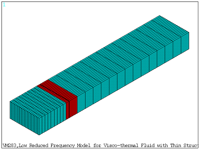
The lengths of room A and room B along the Z-direction are meshed with 10 and 15 FLUID30 elements, respectively. The width is meshed with 20 FLUID30 elements. The aluminum plates are meshed using structural solid shell elements (SOLSH190). The visco-thermal layer between the aluminum plates and the volumes of room A and B are all meshed using pure acoustic elements, except for interfaces with structural solid shell elements. On these interfaces, coupled acoustic elements with fluid-structure interaction (FSI) are applied. Loading is not considered in this model, because transmission loss is calculated from the ratio of average pressures. The infinite radiation impedance boundary condition is specified to absorb waves reflected out of the system.
Results Comparison
The transmission loss (TL) is calculated using the average nodal pressures in room A and across the absorbing boundary of room B, respectively.

The TL value obtained from Mechanical APDL shows the same variation trend versus frequency as depicted in Figure 6.31 in the reference material. The computed TL values at the peaks and troughs are listed with target values obtained from the reference figure.
| Frequency (Hz) | Target (dB) | Mechanical APDL | Ratio |
|---|---|---|---|
| 10 | 29.000 | 28.708 | 1.007 |
| 40 | 0.000 | 0.071 | 1.000 |
| 80 | 22.000 | 21.544 | 1.000 |
| 84 | 20.000 | 20.000 | 1.000 |
| 214 | 51.500 | 49.984 | 0.971 |
| 228 | 8.000 | 7.642 | 0.950 |
| 278 | 34.000 | 32.576 | 0.988 |
| 286 | 24.000 | 22.696 | 0.908 |
| 300 | 28.500 | 26.685 | 0.921 |
Figure 493: Transmission Loss Versus Frequency for the Double Wall Configuration Obtained from Mechanical APDL