VM211
VM211
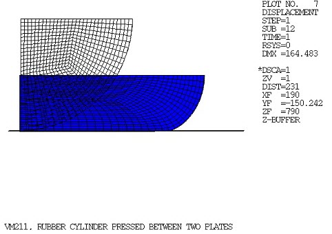
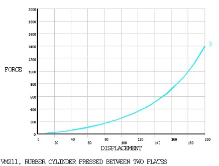
Rubber Cylinder Pressed Between Two Plates
Overview
| Reference: | T. Tussman, K-J Bathe, "A Finite Element Formulation for Nonlinear Incompressible Elastic and Inelastic Analysis", Computers and Structures, Vol. 26 Nos 1/2, 1987, pp. 357-409. | ||||||||
| Analysis Type(s): | Static Analysis (ANTYPE = 0) | ||||||||
| Element Type(s): |
| ||||||||
| Input Listing: | vm211.dat |
Test Case
A long rubber cylinder is pressed between two rigid plates using a maximum imposed displacement of δmax. Determine the force-deflection response.

| Material Properties | Geometric Properties | Loading | |||||||
|---|---|---|---|---|---|---|---|---|---|
|
|
|
Analysis Assumptions and Modeling Notes
This test case solves the problem of VM201 using the 2D and 3D rigid target and contact elements. A plane strain solution is assumed based on the geometry of the problem. Due to geometric and loading symmetry, the analysis can be performed using one quarter of the cross section. All nodes on the left edge (X = 0) are constrained, UX = 0. All nodes on the top edge (y = 0) are coupled in UY. An imposed displacement of -0.1 m acts upon the coupled nodes.
The problem is solved in 12 different ways. The first four solutions are performed using the default contact algorithm, the next four are performed using the Lagrange multipliers method (KEYOPT(2) = 3 ) of contact elements, and the final four are performed using the exponential pressure-penetration relationship (KEYOPT(6) = 3):
The lower-order 2D model used PLANE182 with CONTA172 and TARGE169 elements.
The higher-order 2D model used PLANE183 with CONTA172 and TARGE169.
The lower-order 3D model used SOLID185 with CONTA174 and TARGE170.
The higher-order 3D model used SOLID186 with CONTA174 and TARGE170.
The lower-order 2D model used PLANE182 with CONTA172 and TARGE169 and solved using Lagrange multipliers method.
The higher-order 2D model used PLANE183 with CONTA172 and TARGE169 and solved using Lagrange multipliers method.
The lower-order 3D model used SOLID185 with CONTA174 and TARGE170 and solved using Lagrange multipliers method.
The higher-order 3D model used SOLID186 with CONTA174 and TARGE170 and solved using Lagrange multipliers method.
The lower-order 2D model used PLANE182 with CONTA172 and TARGE169 and solved using the exponential pressure-penetration relationship
The higher-order 2D model used PLANE183 with CONTA172 and TARGE169 and solved using the exponential pressure-penetration relationship.
The lower-order 3D model used SOLID185 with CONTA174 and TARGE170 and solved using the exponential pressure-penetration relationship.
The higher-order 3D model used SOLID186 with CONTA174 and TARGE170 and solved using the exponential pressure-penetration relationship.
Results Comparison
| Target[1] | Mechanical APDL | Ratio | ||
|---|---|---|---|---|
| PLANE182 | Force at Displacement = 0.1 (N) | 250.00 | 243.02 | 0.972 |
| Force at Displacement = 0.2 (N) | 1400.00 | 1362.08 | 0.973 | |
| PLANE183 | Force at Displacement = 0.1 (N) | 250.00 | 244.93 | 0.980 |
| Force at Displacement = 0.2 (N) | 1400.00 | 1372.60 | 0.980 | |
| SOLID185 | Force at Displacement = 0.1 (N) | 250.00 | 241.58 | 0.966 |
| Force at Displacement = 0.2 (N) | 1400.00 | 1359.44 | 0.971 | |
| SOLID186 | Force at Displacement = 0.1 (N) | 250.00 | 252.69 | 1.011 |
| Force at Displacement = 0.2 (N) | 1400.00 | 1399.81 | 1.000 | |
| With KEYOPT (2) = 3 of CONTA172 (dropped midside nodes) | ||||
| PLANE182 | Force at Displacement = 0.1 (N) | 250.00 | 252.57 | 1.010 |
| Force at Displacement = 0.2 (N) | 1400.00 | 1406.84 | 1.005 | |
| With KEYOPT (2) = 3 of CONTA172 | ||||
| PLANE183 | Force at Displacement = 0.1 (N) | 250.00 | 256.10 | 1.024 |
| Force at Displacement = 0.2 (N) | 1400.00 | 1415.80 | 1.011 | |
| With KEYOPT (2) = 3 of CONTA174 (dropped midside nodes) | ||||
| SOLID185 | Force at Displacement = 0.1 (N) | 250.00 | 251.46 | 1.006 |
| Force at Displacement = 0.2 (N) | 1400.00 | 1400.48 | 1.000 | |
| With KEYOPT (2) = 3 of CONTA174 | ||||
| SOLID186 | Force at Displacement = 0.1 (N) | 250.00 | 255.65 | 1.023 |
| Force at Displacement = 0.2 (N) | 1400.00 | 1416.53 | 1.012 | |
| With KEYOPT (6) = 3 of CONTA172 (dropped midside nodes) | ||||
| PLANE182 | Force at Displacement = 0.1 (N) | 250.00 | 242.88 | 0.972 |
| Force at Displacement = 0.2 (N) | 1400.00 | 1366.14 | 0.976 | |
| With KEYOPT (6) = 3 of CONTA172 | ||||
| PLANE183 | Force at Displacement = 0.1 (N) | 250.00 | 244.33 | 0.977 |
| Force at Displacement = 0.2 (N) | 1400.00 | 1357.87 | 0.970 | |
| With KEYOPT (6) = 3 of CONTA174 (dropped midside nodes) | ||||
| SOLID185 | Force at Displacement = 0.1 (N) | 250.00 | 246.01 | 0.984 |
| Force at Displacement = 0.2 (N) | 1400.00 | 1363.66 | 0.974 | |
| With KEYOPT (6) = 3 of CONTA174 | ||||
| SOLID186 | Force at Displacement = 0.1 (N) | 250.00 | 254.11 | 1.016 |
| Force at Displacement = 0.2 (N) | 1400.00 | 1405.32 | 1.004 | |