VM212

VM212
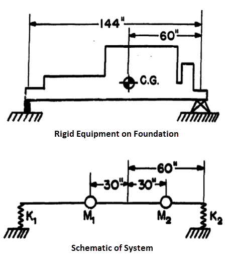
DDAM Analysis of Foundation System (2-DOF System)

Overview

Reference: O’Hara, G.J., Cunniff, P. F., “Interim Design Values for Shock Design of Shipboard Equipment”, NRL Memorandum Report 1396, 1963, p. 10
Analysis Type(s):
Modal Analysis (ANTYPE = 2)
Spectrum Analysis (ANTYPE = 8)
Element Type(s):
Structural Mass (MASS21)
Spring-Damper Combination Element (COMBIN40)
3D 2-Node Beam (BEAM188)
Input Listing: vm212.dat

Test Case

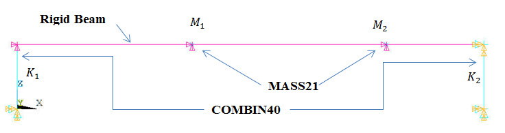
A simple equipment-foundation system is modeled using a spring-damper element (COMBIN40) representing the foundation, a beam element (BEAM188) representing the equipment, and a mass element (MASS21) representing the equipment mass, as shown in Figure 336: Schematic Representation of 2-DOF System (Foundation System).

Shock loading is applied at the fixed base of the foundation system along the athwartship direction. The shock spectrum is based on the ship type, mounting location, direction of shock, and type of design (elastic or elastic-plastic). DDAM analysis is performed on this system to determine natural frequency, deflection, and shock design value.

Figure 336: Schematic Representation of 2-DOF System (Foundation System)

Schematic Representation of 2-DOF System (Foundation System)

Figure 337: Finite Element Representation of 2-DOF System (Foundation System)

Finite Element Representation of 2-DOF System (Foundation System)

Material PropertiesGeometric PropertiesLoading
Equipment weight, W = 20,000 lb
Mass, M1 (and M2) = 10,000 lb
Spring constant, K1 = 1.3 x 10⁶ lb/in
Sprint constant, K2 = 3.9 x 10⁶ lb/in
Foundation material, E = 1.0 psi
Length = 144 in
Beam with arbitratry section
Area = 100 in2
Moment of inertia along Y and Z = 833 in⋅lb⋅sec2
Thickness along Y and Z = 10 in
Acceleration spectrum computation constants (ADDAM)
AF = 0.4
AA = 10.0
AB = 37.5
AC = 12.0
AD = 6.0
Velocity spectrum computation constants (VDDAM)
VF = 0.2
VA = 30.0
VB = 12.0
VC = 6.0

Analysis Assumptions and Modeling Notes

The equipment is assumed to be rigid. As only unidirectional motion is being considered, the rigid equipment is divided into two equal masses located about the center of gravity such that where Ig is the moment of inertia of the equipment at the center of gravity and di is the distance to the mass from the center of gravity.

The fixed support condition is applied at the base of the foundation system. At node 40, only UZ and ROTY DOF are being considered, while other DOFs are constrained.

Results Comparison

TargetMechanical APDLRatio
f1, Hz46.30046.3331.001
f2, Hz114.000114.0361.000
Mode #1
Node = 20, UZ, Deflection, in0.16290.16291.000
Node = 30, UZ, Deflection, in0.10990.10991.000
Mode Coefficient0.19310.19310.999
Participation Factor7.06597.06591.001
Shock Design Value, D1, in/sec2 2316.0002316.0001.000
Mode #2
Node = 20, UZ, Deflection, in0.10990.10991.000
Node = 30, UZ, Deflection, in0.16290.16291.000
Mode Coefficient0.02180.02181.000
Participation Factor1.37301.37351.000
Shock Design Value, D2, in/sec2 8133.0008132.87131.000