59.5. Boundary Conditions and Loading

The following topics about applying boundary conditions (BCs) and loading are available:

59.5.1. Steady-State Thermal Analysis: BCs and Loading

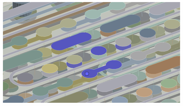
Internal heat generation loads are applied to selected MESH200 element components representing the embedded copper traces and vias:

Figure 59.4: Internal Heat Generation of 2 W/mm3 Applied on Selected Surface MESH200 Elements

Internal Heat Generation of 2 W/mm3 Applied on Selected Surface MESH200 Elements

Figure 59.5: Internal Heat Generation of 0.1 W/mm3 Applied on Selected Line MESH200 Elements

Internal Heat Generation of 0.1 W/mm3 Applied on Selected Line MESH200 Elements

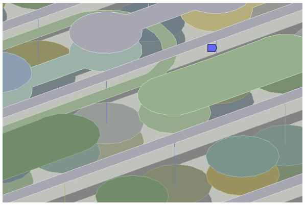
After the reinforcings have been created (EREINF) from MESH200 and base-element intersections, the boundary conditions applied on MESH200 are transferred to the smeared reinforcing members (BFPORT):

Figure 59.6: Internal Heat Generation of 2 W/mm3 Transferred from Surface MESH200 to Generated REINF265 Members
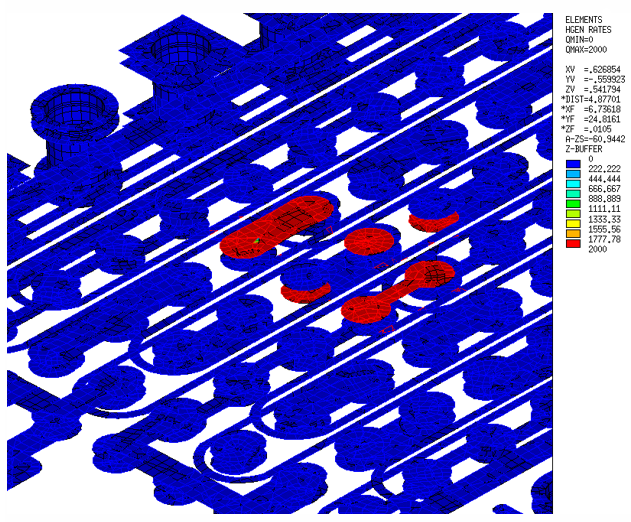
Internal Heat Generation of 2 W/mm3 Transferred from Surface MESH200 to Generated REINF265 Members

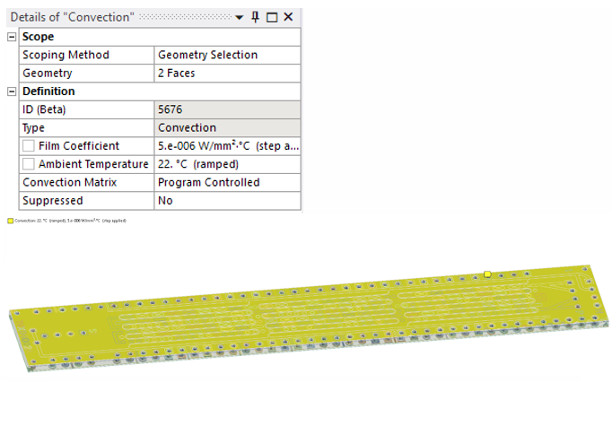
Convection boundary conditions are applied on the top and bottom faces of the PCB:

Figure 59.7: Details: Convection Boundary Conditions

Details: Convection Boundary Conditions

59.5.2. Downstream Structural Analysis: BCs and Loading

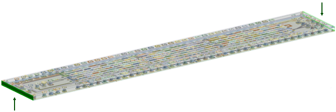
The ends of the PCB are constrained for all displacement degrees of freedom (indicated in green):

Figure 59.8: Structural Boundary Constraint Locations

Structural Boundary Constraint Locations