


The 3D crimp joint model consists of a 0.5 mm thick grip and seven stranded wires, with each wire having a 0.725 mm diameter. The grip and wires are made of a copper alloy which is modeled by the multi-linear isotropic hardening plasticity material model. The model also includes a rigid punch and a rigid support.
The steps to create this model are broken down as follows:
The grip and the seven stranded wires are modeled with SOLID186 (3D structural solid) elements.
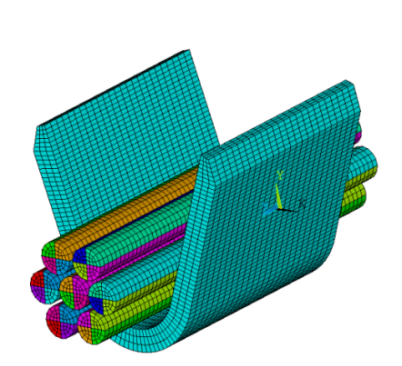
The rigid punch and rigid base supports are modeled with TARGE170 (3D target segment) elements.
The rigid target surfaces are taken from a pair-based contact model and converted
to general contact. To include these target surfaces in the general contact
definition, a zero real constant ID and a zero material ID are assigned via
EMODIF with I1 = GCN. A unique
section ID (SECNUM) and a unique element type ID
(TYPE) are also assigned via EMODIF. The
same ID number is used for the section and element type IDs.
! Defining the rigid punch as a general contact surface

ESEL,S,REAL,,32          ! Select the existing rigid surface for the punch
EMODIF,ALL,SECNUM,32     ! Assign a unique section ID (same as type ID)
EMODIF,ALL,REAL,GCN      ! Assign a 0 REAL ID by inputting the GCN label
EMODIF,ALL,MAT,GCN       ! Assign a 0 MAT ID by inputting the GCN label
ESURF,ALL,REVE           ! Reverse the normal for proper definition

! Defining the rigid base as a general contact surface

ESEL,S,REAL,,35          ! Select the existing rigid surface for the base
EMODIF,ALL,SECNUM,35     ! Assign a unique section ID (same as type ID)
EMODIF,ALL,REAL,GCN      ! Assign a 0 REAL ID by inputting the GCN label
EMODIF,ALL,MAT,GCN       ! Assign a 0 MAT ID by inputting the GCN label
ALLSEL,ALL
Alternatively, you could generate these target surfaces yourself (AMESH) if you were modeling this structure from scratch.
After building a complete finite element model and defining rigid targets, the
next step is to generate general contact surfaces (GCGEN). The
program generates 3D surface-to-surface elements
(CONTA174) on exterior faces of the base elements and
splits them into different contact surfaces (each having a unique section ID) if the
angle between the normal of adjacent faces is greater than the specified feature
angle (GCGEN with FeatureANGLE = 20).
It also generates 3D line contact elements (CONTA177) on
the feature edges between split surfaces (based on GCGEN with
EdgeKEY = 1).
The value 20 is used for feature angle in order to achieve the desired split of the contact surfaces and edges between them. In this model, only the top edges of the grip are considered, and the rest are deleted.
allsel,all
gcgen,,20,1,      ! Automatically generate CONTA174 elements on
                  ! exterior faces & CONTA177 on feature edges

! Only the top edges of the grip are considered, and the rest are deleted

esel,s,real,gcn      ! Select general contact elements
esel,r,ename,,177    ! Reselect the edge elements, CONTA177
esel,u,sec,,95,96    ! Unselect the top edge elements
esel,u,sec,,109,112  ! Unselect the top edge elements
edele,all,all        ! Delete the selected edge elements except top
                     ! edge elements
allsel,all

! Define the contact force-based model for CONTA177

keyopt,95,3,0
keyopt,96,3,0
keyopt,109,3,0
keyopt,110,3,0
keyopt,111,3,0
keyopt,112,3,0
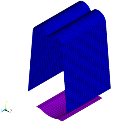
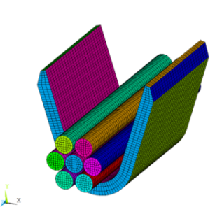
Figure 42.4: Surface Contact Elements (a) and Edge Contact Elements (b)
 |
 |
| (a) Surface Contact Elements | (b) Edge Contact Elements |
Next, the contact interactions are defined (GCDEF).
By default, frictionless standard contact is assumed among all general contact surfaces. To override the default, GCDEF,AUTO,ALL,ALL,100,100 defines frictional contact for all contact surfaces.
Additional GCDEF commands are used to exclude some surfaces that may cause spurious contact.
! Define interactions between general contact surfaces via GCDEF

gcdef,auto,all,all,100,100   ! Define auto asymmetric frictional contact
                             ! among all surfaces defined by material ID 100
mp,mu,100,.1                 ! Define friction coefficient for material ID 100
tb,inter,100,,,standard      ! Define standard contact behaviour
tbdata,1,0                   ! Include penetration and gap

r,100
rmodif,100,3,1               ! Define FKN for real ID 100

! Exclude contact between some surfaces via GCDEF
! to avoid spurious contact

gcdef,exclude,grip_zp_face,all_face
gcdef,exclude,grip_zn_face,all_face
gcdef,exclude,grip_zp_face,all_edge
gcdef,exclude,grip_zn_face,all_edge
gcdef,exclude,gripTop_xn_face,grip_inner_face
gcdef,exclude,75,77
gcdef,exclude,gripTop_xp_face,grip_inner_face
gcdef,exclude,76,79
allsel,all

gcdef,list                ! List all defined interactions between
                          ! general contact surfaces