


This section covers the following modeling topics:
To better demonstrate the benefits of using general axisymmetric elements in models having both axisymmetric and nonaxisymmetric components, two models are analyzed and compared:
Because the shaft and valve components of the camshaft are axisymmetric, but the cams are not, the model is simplified by combining axisymmetric and full 3D modeling concepts. The following model shows the geometry of the simplified camshaft assembly, which now has a 2D shaft and a 2D valve:
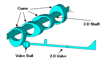
The 2D valve and 2D shaft are modeled with general axisymmetric SOLID272 elements. Because the valve and shaft should not have high localized deformation in the circumferential direction (θ), the number of Fourier nodes is set to 3. (The SOLID272 element's KEYOPT(2) option controls the number of Fourier nodes in the circumferential direction.)
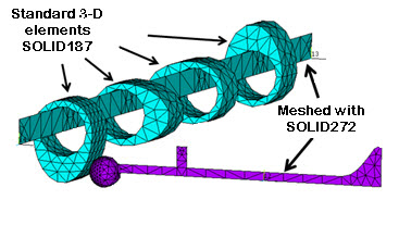
The remaining parts of the assembly such as the valve ball and cams are modeled with standard 3D elements (SOLID187 in this case), as shown:
Before generating the 3D mesh (based on the 2D mesh) on the master plane, axes of symmetry for the valve and shaft are defined separately (via SECTYPE and SECDATA commands), as follows:
Defining valve axis of symmetry:
SECTYPE,1,AXIS,,valve      ! Here "valve" is a user-specified name
SECDATA,x1,y1,z1,x2,y2,z2  ! Coordinates of two points to define axis of valve
Defining shaft axis of symmetry:
SECTYPE,2,AXIS,,shaft      ! Here "shaft" is a user-specified name
SECDATA,X1,Y1,Z1,X2,Y2,Z2  ! Coordinates of two points to define axis of shaft
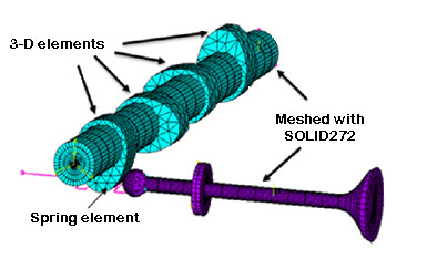
After defining the axes of symmetry, the NAXIS command generates the 3D mesh, as shown:
This model uses the full camshaft assembly as shown in Figure 7.1: Full 3D Geometry of a Camshaft Assembly. The purpose for analyzing the full 3D model is simply to better illustrate the efficiency, and to verify the accuracy, of the general axisymmetric model.
All components of the assembly are modeled with standard 3D elements (SOLID187 in this case), and all boundary conditions, loadings, material properties, solution settings and hardware settings are identical to the general axisymmetric model.
A comparison of the analysis results based on the general axisymmetric model and the full 3D model appears in Results and Discussion.
Contact pairs couple general axisymmetric elements with standard 3D elements. A node-to-surface contact element represents contact between two surfaces by specifying one surface as a group of nodes.
Because the SOLID272 general axisymmetric element has nodes (and not elements) in 3D space after the NAXIS command has generated the 3D mesh, the CONTA175 2D / 3D node-to-surface contact element is a good choice for making contact pairs.
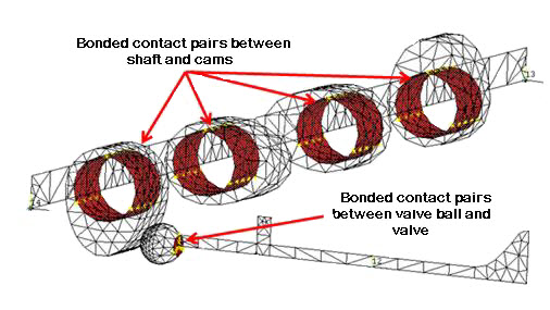
As shown in the following figure, bonded contact pairs with the MPC algorithm are defined to couple the shaft with the cams and the valve ball with the valve. The bonded contact pairs connect the general axisymmetric elements SOLID272 with the standard 3D elements SOLID187.
The following example input shows how to create the contact pairs between the shaft and cams:
ET,1,175                     ! Define CONTACT175 element
ET,2,170                     ! Define TARGET170 element
KEYOPT,1,12,5                ! Bonded Contact
KEYOPT,1,2,2                 ! MPC style contact
CMSEL,S,SHAFT_NODES          ! "SHAFT_NODES" is the user-defined nodal component
                             ! which has all the nodes of the shaft that are in
                             ! contact with cams
TYPE,1
REAL,1

! Small loop to create contact elements on selected nodes

NN=0
*GET,NUMN,NODE,,COUNT
*DO,I,1,NUMN
  NN=NDNEXT(NN)
  E,NN                       ! Create contact elements on nodes one by one.
*ENDDO

CMSEL,S,CAM_NODES            ! Select cam nodes and elements at the contact region
ESLN
TYPE,2
REAL,1
ESURF                        ! Create contact pair between shaft and cams
Similarly, the other bonded contact pair is defined between the valve and valve ball.
A spring is modeled using the COMBIN14 element (as shown in Figure 7.4: Meshed Camshaft Model After Generating the 3D Mesh). The spring ensures that the valve maintains contact with the shaft during analysis. One end of the spring is attached to the valve via the bonded contact pair; the other is fixed in all degrees of freedom.
In the following figure, a standard surface-to-surface contact pair using the augmented Lagrangian algorithm is defined between the cam and valve ball. Also shown are two revolute joints (one at either end of the shaft).
Figure 7.6: Revolute Joints and Surface-to-Surface Contact Pair
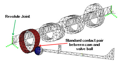
Shown are two revolute joints (one at each end of the shaft) and a surface-to-surface contact pair between the cam and valve ball.
CONTA174 and TARGE170 elements are used in the contact pair between the cam and valve ball. The status of this contact pair changes during analysis.