


The following illustration shows the deformation plots (USUM) of the camshaft assembly at various time steps during one full rotation (θ = 360 degrees) of the shaft:
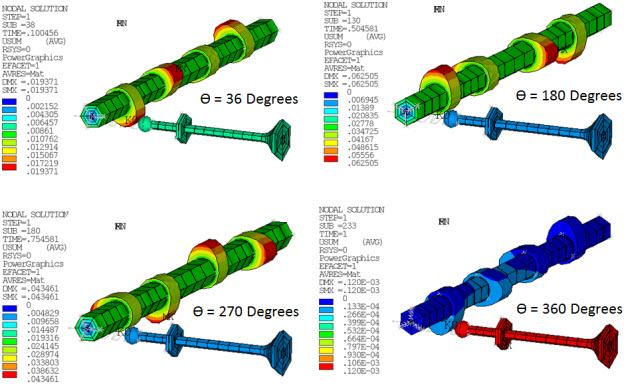
The plots show that the valve always remains in touch with the cam throughout the analysis.
The following figure shows the maximum and minimum principal stress plots of the valve and shaft at the end of the analysis:
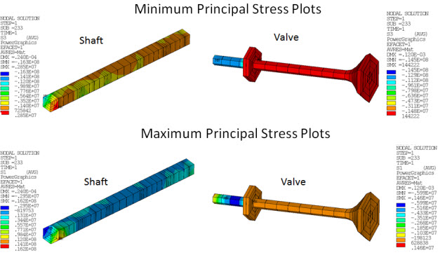
The shaft and valve are subjected to nonaxisymmetric deformation. The results show that general axisymmetric elements are capable of modeling nonlinear general 3D deformation. The problem also demonstrates how general axisymmetric elements can have any axis as the axisymmetric axis.
To verify the accuracy and efficiency of the general axisymmetric element model, a transient analysis was performed on the full 3D model of the crankshaft assembly. Both the general axisymmetric model and the full 3D model simulations were run on the same computer. Solution settings for both models were identical.
The following figure shows a direct comparison of results between the full 3D model and the general axisymmetric model:
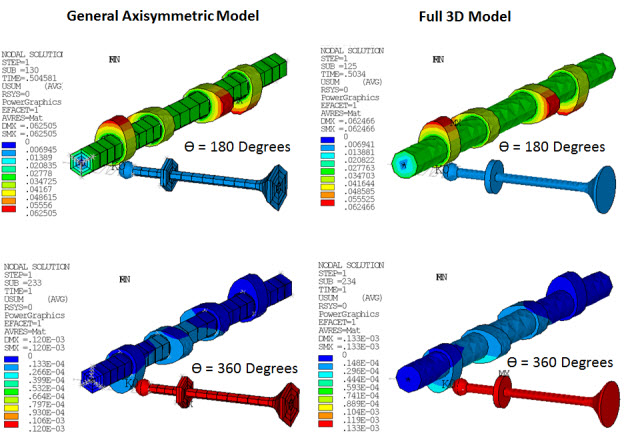
In the full 3D model, the number of degrees of freedom (DOFs) is approximately 300,000. In the general axisymmetric model, the number of DOFs is only 18,000. The smaller number of DOFs in the general axisymmetric model is possible due to the combination of axisymmetric and 3D modeling.
Following is a comparison of the general axisymmetric model and the full 3D model in terms of computational efficiency:
| FEA Model Details | General Axisymmetric Model [1] | Full 3D Model [2] |
|---|---|---|
| Number of elements in FEA model | 4140 | 8473 |
| Number of elements in valve component | 69 | 1632 |
| Number of elements in shaft component | 102 | 3453 |
| Number of elements in valve ball component | 1158 | 1122 |
| Number of elements in cams | 1769 | 1769 |
| Simulation time | Simulation time for the general axisymmetric model is observed to be approximately 55 percent less than that of the full 3D model. | |
In the general axisymmetric model, the valve and shaft components are meshed with general axisymmetric SOLID272 elements. The remaining components consist of standard 3D elements.
In the full 3D model, all components are meshed with 3D elements.
The analyses show that using general axisymmetric elements can reduce computational time significantly with no loss of accuracy.