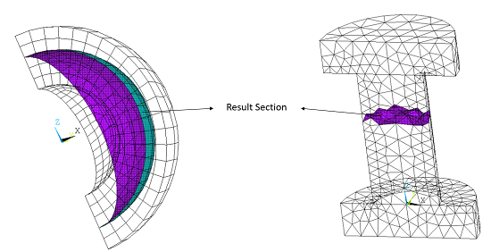
A result section is a user-defined surface that can be used to output and monitor section forces, moments, heat flow, current, mass flow, and pore fluid volume flux during a solution. Surface-to-surface contact elements are used to define the result section.
The following result section topics are available:
Result section output is available for surfaces defined using 2D or 3D surface contact elements, CONTA172 or CONTA174. KEYOPT(4) of the contact elements must be set to 1 or 2, and all the contact elements in the section must have the same real constant ID. No other key options are used, and no real constants are used for contact elements in the result section.
The contact elements must be overlaid on faces of 2D or 3D continuum elements. Other types of elements (beams, shells, springs, etc.) can be attached to the section but are not part of the result section definition.
The result section does not need to be flat. The underlying solid elements can have any shape: triangle, quadrilateral, tetrahedron, wedge, or hexahedron.
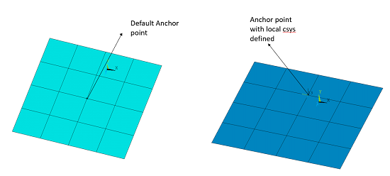
Each result section is associated with a local coordinate system as well as an anchor point, which is the origin of the local coordinate system. You can allow the program to compute the original location of the anchor point and the local coordinate system, or you can specify them directly.
By default, the program computes the geometry center point as the anchor point location. The default local coordinate system is based on the singular-value decomposition (SVD) approach. The positive local x-direction points to the surface normal of the result section in an average sense. The default coordinate system is particularly useful when the section is flat or almost flat. The default coordinate system can be used when the section is curved, but it may not be adequate for such cases.
As an alternative to the default anchor point, you can specify one by defining a pilot node. The pilot node is a target element (TARGE169 for 2D, TARGE170 for 3D) having a target element shape code of PILO (see the TSHAP command). The target element must have the same real constant ID as the other contact elements in the result section. The coordinates of the pilot node are used as the anchor point location, and the local coordinate system follows the nodal coordinate system of the pilot node.
Updating Anchor Point Position and Local Coordinate System Orientation
In a large deflection analysis, the result section may move and rotate significantly during the deformation. KEYOPT(4) of the contact element type provides two possible ways to account for this motion:
KEYOPT(4) = 1 - The anchor point moves and the local coordinate system rotates with the average rigid body motion of the contact elements used to define the result section. This is the default behavior.
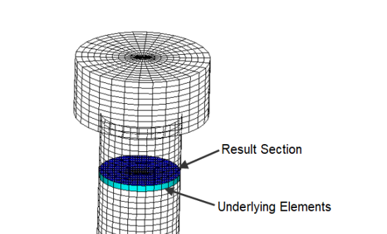
KEYOPT(4) = 2 - The anchor point moves and the local coordinate system rotates with the average rigid body motion of the underlying elements (those under the contact elements).
Calculation of the section results (such as the total forces) involves nodal quantities associated with elements on one side of the section only. This is illustrated in the figure below.
Since the section usually cuts through the solid element mesh, manual generation of the section may not be straightforward. The easiest way to generate the result section is via the RSMESH command.
RSMESH defines the result section and automatically imbeds the contact elements on the surface of certain elements in the currently selected set of elements. The exact location and orientation of the result section is determined by various input quantities on the RSMESH command:
RSMESH, P0,
RID, KCN,
Kdir, VALUE,
NDPLANE, PSTOL,
Ecomp
To define the cutting direction, you must identify a local coordinate system along with either a node on the section or a cutting location. There are several ways to achieve this, as described below.
Cutting Location in a Specified Coordinate System
(VALUE on RSMESH)
By this method, the RSMESH command creates a result section in
the defined direction (Kdir) of the specified coordinate
system (KCN) at the cutting location given by
VALUE.
LOCAL,11,,0,.5,0               ! Local coordinate system #11 with origin at (0,0.5,0)
RSMESH,,3,11,y,.5,,,elgroup    ! Result section based on local y = 0.5
Node on the Cutting Plane (NDPLANE on
RSMESH)
By this method, the RSMESH command creates a result section in
the defined direction (Kdir) at the node specified by
NDPLANE.
N,35,0,.5,0                  ! Node 35 defined at location (0,0.5,0)
RSMESH,,3,,y,,35,,elgroup    ! Result section based on y location of node 35
User-Defined Anchor Point (P0 on
RSMESH)
For this method, you must define a pilot node (target element
TARGE169 or TARGE170) before
issuing the RSMESH command. RSMESH then
creates the result section using the position and nodal coordinate system of the
pre-defined pilot node. The result section contact elements are assigned the same
real constant ID as the target element. For this method, the command arguments
RID, KCN,
Kdir, VALUE, and
NDPLANE are ignored.
N,10,0,0,0                  ! Define a node
ET,2,170                    ! Element type 2 is TARGE170
R,2                         ! Define real constant set 2
TYPE,2                      ! Element type number 2
REAL,2                      ! Real constant set number 2
TSHAP,pilo                  ! Target segment shape is pilot node
E,10                        ! Create target element (pilot node)
RSMESH,10,,,,,,,elgroup     ! Result section based on the pilot node
By default, result section output is suppressed. To activate result section
output, you must issue the command
OUTPR,RSFO,Freq, where
Freq indicates the desired output frequency (every
substep or load step). The output is written to a single
Jobname.secf text file.
The section results include the following output quantities:
|
|
The section moments are computed based on the current position of the anchor point and current orientation of the local coordinate system. The coordinates of the current anchor point are updated during a large deflection analysis.
Tracking Result Items During Solution
You can also monitor the following result section quantities during solution via
the NLHIST command with Key = RSEC,
Item = REST, and Node set
to the real constant ID value associated with the result section:
Comp
Label on NLHIST
| Quantity |
| SECF | Total section force |
| SECM | Total section moment |
| AXST | Section axial stress |
| BDST | Section bending stress |
| SPTX | Section center X coordinate |
| SPTY | Section center Y coordinate |
| SPTZ | Section center Z coordinate |
| THXY | Rotation about local z |
| THYZ | Rotation about local x |
| THZX | Rotation about local y |
The specified result quantities are written to the file
Jobname.nlh only at time points specified via the
OUTPR,RSFO,Freq command.
Result section output is subject to the following limitations:
Section output is available only for surfaces defined by CONTA172 or CONTA174 contact elements overlaid on faces of 2D or 3D continuum elements. When computing section output quantities, underlying elements on only one side of the section are used.
The total force and the total moment in the result section are computed based on the summation of nodal forces of underlying elements attached to nodes on the result section. However, when comparing postprocessing results using the FSUM command, a result discrepancy may be obtained if any displacement constraints (CE or CP) are applied on those nodes.
Depending on which side of the surface is used to define the result section, result differences in certain output quantities may be observed.
Result section output is not available if the result section is defined inside a substructure.
The element type ID and real constant set ID used for the result section should not be used for any other purpose, such as contact analysis, remote loading, and so on.
Bending stress is calculated by assuming the section is circular for 3D and rectangular for 2D. Bending stress in the axisymmetric case should not be considered because it might calculate a moment where none exists, similar to the FSUM command.
This example demonstrates the procedure used to output result section data. The model used is similar to Bolt Thread in the Technology Showcase: Example Problems.
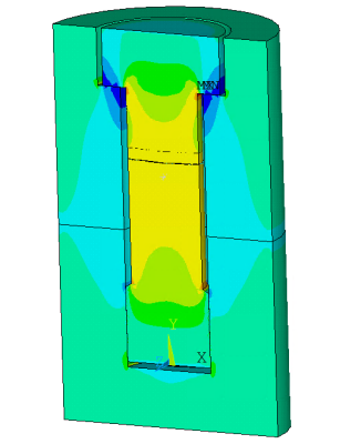
This 3D model represents an M120 structural steel bolt with standard thread dimensions. The model includes a cover plate and a base plate. A bilinear isotropic plastic material model is used for the bolt and the plates.
The 3D model is generated by extruding the 2D axisymmetric model about the Y-axis with the EEXTRUDE command. SOLID186 structural solid elements are used.
EEXTRUDE,,30,,,360 ! Create 3D model by rotating 2D axisymmetric model about y-axis
The steps used to define the result section and review the result section data are described below.
Define the Result Section
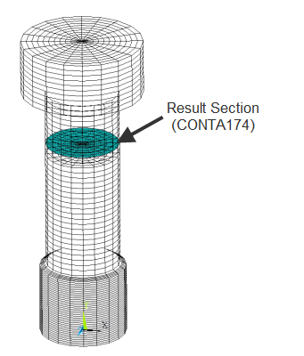
Use the RSMESH command to generate a result section. This command defines the result section and automatically imbeds the contact elements (CONTA174 with KEYOPT(4) = 1) on the surface of base elements. The command input shown below creates a result section within the bolt at location y = 280 in the active coordinate system. In this example, RSMESH also creates an element component named "elgr" that contains the underlying base elements.
/PREP7
ESEL,S,TYPE,,105   ! Select the bolt elements
RSMESH, , ,,y,280,,,elgr
Output the Results Section Data
By default, result section output is suppressed. Issue the command
OUTPR,RSFO,Freq to activate result
section output and write it to the Jobname.secf file.
/SOLU
OUTPR,RSFO,5          ! Define the frequency to output results
The axial stress is tensile in the bolt and compressive in the portion of the plates compressed by the bolt heads.
Section axial stress at y = 280 is -330.1781, as output in the Jobname.secf file shown below. (Note that columns 8 through 11 have been removed from this .SECT file to improve readability.)


