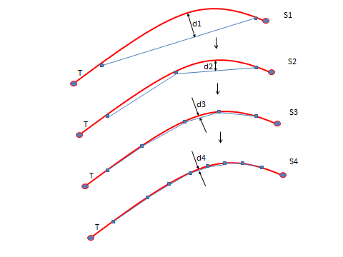
The following methods are available for generating a new mesh:
This method for generating a new mesh supports both 2D and 3D elements. Splitting occurs first for mesh refinement (although for the contact-based criterion with wearing, only morphing is needed).
In 2D meshes, mesh morphing occurs after mesh splitting. The morphing operation can also modify elements that have not been split. The morphing process attempts to improve the element distortion metrics by optimizing the metrics immediately following splitting. If the shape metrics of specific elements cannot be improved without sacrificing the quality of the neighboring elements, then the element is not changed via morphing. The morphing process is iterative and converges when a maximum number of iterations (set automatically depending on problem size and element type) are reached or no further element shape quality enhancement is possible. Morphing works by moving the nodes in the mesh (except for the nodes on the boundary).
In 3D tetrahedron splitting, cotangent-weighted Laplacian mesh smoothing and topology correction (by 2-3, 3-2, 2-2, and 4-4 face swaps) occur automatically after splitting. 3D mesh refinement is more tolerant of large deformation and mesh distortion than the same 2D process because of the additional topology-correction step. As in the 2D case, morphing in 3D does not change node locations on the boundary; however, topology correction may modify elements on the boundary.
When the energy- or position-based criterion is used, solid elements are split directly and appropriate transitional elements are generated around a split region to ensure compatible transition with the unsplit regions. In such cases, parent elements within a component are split and the child elements are automatically made part of the component. Parent elements are dissociated from the component and removed from the simulation database during the splitting procedure. In this way, component information is automatically transferred from parent to child elements during the splitting procedure. For more information, see Geometry Details for Mesh Splitting .
Elements supporting contact-based criteria are TARGE169, TARGE170, CONTA172, and CONTA174. Nonlinear mesh adaptivity has restrictions for contact and target elements.
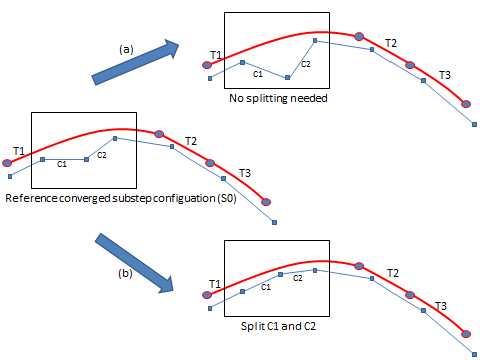
For contact-based criteria that use the NUMELEM criterion option (NLADAPTIVE,,,NUMELEM), the candidate solid elements for splitting are selected indirectly. Nonlinear adaptivity criteria are applied to components of target elements and the decision to split the corresponding contacts is dependent on solution-based quantities at the specific substep at which criteria-checking occurs. For example, consider the following figure, showing a 2D target-contact interface at a subset on which contact-based nonlinear mesh adaptivity criteria are checked:
The nonlinear mesh adaptivity algorithm associates contact and target elements
with each other using pinball radius values. For two components, CM1 and CM2 (where
CM1 is consists of target element T1, and CM2 consists of both target elements T2
and T3), the following associations are made (where Ci
and Ti are the ith contact and
jth target elements, respectively) :
| C1 | C2 | C3 | C4 | C5 | C6 | |
|---|---|---|---|---|---|---|
| T1 (CM1) | Y | Y | Y | Y | - | - |
| T2 (CM2) | - | - | - | Y | Y | - |
| T3 (CM2) | - | - | - | - | Y | Y |
Whether splitting or refining contact elements, the program’s decision to do so is determined by checking the total number of contact elements associated with a single target element of a particular target component, and the user-defined number of desired contact elements (NLADAPTIVE,,,,NUMELEM). The following commands assign the desired number of contact elements to be 3 and 5 for individual target elements of CM1 and CM2, respectively:
nladaptive,CM1,add,contact,numelem,3
nladaptive,CM2,add,contact,numelem,5
If the total number of contact elements assigned to a target element is smaller than the desired (user-defined) number during a substep where nonlinear mesh adaptivity criteria are checked, splitting or refining occurs. If the total number of contact elements is greater than the desired number, no further refinement occurs.
A size check exists for contact-based criteria that use the NUMELEM option. The desired size of contact elements associated with a given target element component is calculated by approximately dividing the average target element size (in the component) by the desired number of contact elements.
Example 2.4: Desired Size of Contact Elements
The desired size S for component CM1 above is S = (size of T1) / 3.
If the associated contact element size is less than 0.75 * S (the desired scaled-average size for CM1), no further refinement occurs on the element.
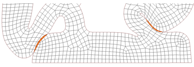
The NUMELEM criterion option for contact-based nonlinear mesh adaptivity is used primary for gap-filling simulation (such as a rubber-seal simulation). Successive refinements of a mesh reduces the maximum gap significantly:
Besides size and number requirements, the decision to split an underlying solid element at a given substep also depends on the relative penetration or gap status of the corresponding contact element with respect to a previous reference substep:
If the penetration increases (gap reduces), the contact element is moving toward the target, and therefore the underlying solid element is split or refined to estimate a smaller pinball radius and improve gap reduction. In other cases, the underlying solid element is not split or refined.
For a successful remeshing or splitting to occur, the contact element must satisfy all of the following criteria:
The number of contact elements associated to a given target element component must be less than the desired (user-defined) number of elements (NLADAPTIVE,,,,NUMELEM) on that component.
The size of the contact element must be greater than the desired scaled-average size for that component (NLMESH,SRAT,,
VAL2).The contact element must be moving toward the target elements in the components (based on the deformation history).
In certain cases, transitional elements can affect the size and number of contact elements generated only when splitting is used. One such case occurs when neighboring target elements belong to different components with different size criteria. Consider the following simulation:
Figure 2.31: Effect of Transitional Element Generation on Size and Number of Contact Elements Generated
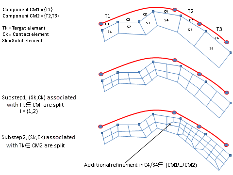
In this case, CM1 and CM2 are the two defined components. CM1 consists of target element T1, and CM2 consists of both target elements T2 and T3. The following nonlinear mesh adaptivity commands are issued:
nladaptive,CM1,add,contact,numelem,6
nladaptive,CM2,add,contact,numelem,4
Because T2 and T3 are of a much smaller size than T1, the size allowance of contact elements scoped to CM2 is much smaller than that of CM1. In substep 1, contact elements scoped to both CM1 and CM2 are candidates for refinement. In substep 2, however, only contact elements scoped to CM2 are candidates, while contact elements scoped to CM1 are not refined. Because transitional elements are generated for compatibility, some contact elements scoped to CM1 may be refined as an indirect consequence of refinements to the CM2 contacts. The program allows a small tolerance for the size criteria so that transition regions do not become over-refined during splitting.
For the mesh-quality-based criterion (NLADAPTIVE,,,MESH), general remeshing is applied to repair the mesh quality or to modify the mesh size and size gradient. The regions to remesh are initialized by seed elements. For 3D models, seed elements have a skewness >= a specified threshold and (for SOLID187 and SOLID227) a Jacobian ratio <= a specified threshold (NLADAPTIVE,,,MESH,SKEWNESS). For 2D models, seed elements have a shape metric of maximum corner angle >= a specified threshold (NLADAPTIVE,,,MESH,SHAPE).
For the contact-, energy-, or position-based criterion (NLADAPTIVE,,,CONTACT / ENERGY / BOX), general remeshing is applied to refine and/or coarsen (for some criteria) the elements in the region defined by seed elements.
When the remeshing criterion is satisfied at a given substep of a load step during a nonlinear adaptive solution, the program creates a source mesh (based on the deformed mesh) for use by the remesher. The source mesh contains the seed elements (elements selected through the requirements of an active criterion), with additional elements included based on the specified number of sculpting layers. Using the source mesh, the remesher attempts to generate a new mesh, or target mesh, of better quality. If the target mesh is better than the source mesh, the solution continues using the new mesh.
Depending on the seed elements and sculpting layers, it is possible that the remeshing domains cover the whole mesh or some partial mesh of the source model.
The following topics general-remeshing topics are available:
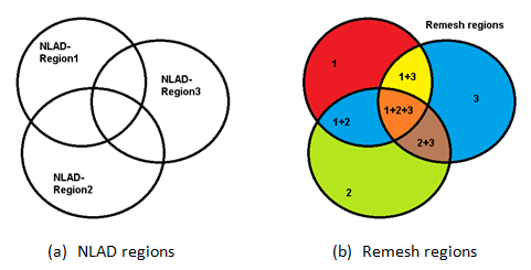
A nonlinear adaptivity (NLAD) region is a group of elements which you can select or assign from geometry parts or bodies.
A remeshing region is a group of elements from the source mesh, where the elements have unique material- and element-component properties. The remeshing region is the atomic 2D or 3D remeshing volume in the remeshing process; the interface surfaces between regions are enforced to a conformal mesh.
An element in a remeshing region may belong to multiple NLAD regions:
Remeshing regions are driven by your defined NLAD regions. Understanding the relationship between NLAD regions and remesh regions is useful when modeling workarounds for self-contact penetration in 3D models.
A remeshing domain is a grouping of elements, each connected by at least one element face in a 3D model, or by at least one element edge in a 2D model.
For a 3D model, no face connection exists between domains, but node or edge connections can exist. For a 2D model, no edge connection exists between domains, but node connections can exist.
A domain can contain multiple regions, composed of a grouping of elements, each connected by at least an element face but having unique material- and element-component properties.
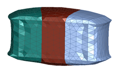
The following figure shows a 3D model composed of six parts, naturally decomposed to six domains:
The two cubes in the figure have edge connections only, so they decompose into two domains for remeshing because they have no face connection.
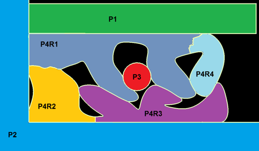
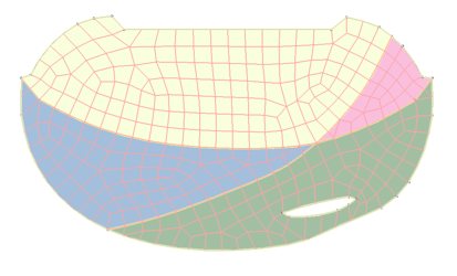
The following figure is a 2D model composed of four domains, where interfaces between the domains can be in contact, but no mesh connections (no conforming meshes) exist. Part 4 (P4) is composed of 4 regions (P4R1 through P4R4).
Remeshing domains are logical 2D/3D geometries composed of parts to remesh, whereas remeshing regions are the effective and specific 2D/3D geometry parts to remesh. The program maintains the interfaces between regions so that the source mesh material and element components are maintained.
Partial model remeshing is an option for minimizing the solution time. The meshing algorithm ensures a conformal mesh between the remeshed regions and untouched regions.
Figure 2.35: Understanding 3D Regions shows one 3D domain consisting of three regions, and Figure 2.36: Understanding 2D Regions shows one 2D domain consisting of four regions:
The program detects remeshing regions and domains according to the seed elements and the specified number of sculpting layers. The elements to be remeshed will therefore have the same element and material properties as the seed elements. Depending on the seed elements and the specified number of sculpting layers, it is possible that the remeshing domains cover the whole mesh or some partial mesh of the deformed model during solution.
Partial model remeshing is an option for minimizing the solution time. The meshing algorithm ensures a conformal mesh between the remeshed regions and untouched regions.
If desired, more granular control of the source mesh geometry is available. NLMESH offers global remeshing controls that apply to every remeshing throughout a load step of the nonlinear analysis. For even more control of the remeshings within a load step, you can perform a restart analysis by modifying the remeshing controls.
The following remeshing-control topics are available:
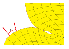
User-specified boundary-angle and edge-angle thresholds are available (NLMESH,BDRA and NLMESH,AEDG, respectively).
The program detects the most appropriate mesh segmentations and remeshes specific 2D or 3D mesh entities using a systematic bottom-up approach. Conformal mesh interfaces between regions are guaranteed, and new nodes on exterior surface are guaranteed to be located on the exterior linear or quadratic facets of the source mesh.
The boundary angle (NLMESH,BDRA) is the outer normal vector angle from two adjacent facets, where a facet is an element face (3D) or an element edge (2D). The boundary angle for a quadratic element (SOLID187) is based on the facet normal direction difference at the edge midside node between two adjacent elements.
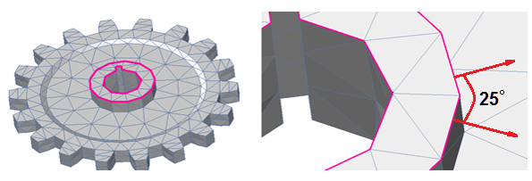
For 3D models, the edge angle (NLMESH,AEDG) is the outer normal vector angle from two adjacent boundary edges in a 3D patch.
Consider this example 3D model:
When the specified threshold value for the edge angle (NLMESH,AEDG) exceeds 25 degrees, the remesher has more freedom to remesh. In this case, the highlighted feature may be lost after remeshing, as it is no longer necessary for the node to be retained based on your input. The same applies to boundary angles (NLMESH,BDRA). Too large a value (typically > 40) can result in a loss of certain features that you had expected to retain after remeshing, and may affect solution convergence adversely.
Use sculpting layers to detect remeshing regions starting from detected seed elements. Specifying a larger number of layers results in relatively large regions containing more elements and causes segregated regions to be merged. If the specified number of layers is large enough, the entire domain is remeshed if it has at least a seed element detected. Using this control helps to avoid many tiny cavities in the remeshing regions.
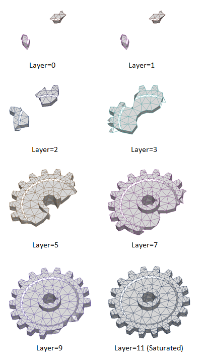
The following figure shows the relationship between the remeshing region, the seed elements, and the specified number of sculpting layers:
A generic approach to partial remeshing begins with one or two seed elements (usually highly distorted elements). When Layer = 0, the remeshing region is composed of seed elements only. By increasing the number of sculpting layers (NLMESH,NLAY), the remeshing region becomes larger until it applies to the entire model. The FEA meshing engine remeshes the regions and guarantees a mesh interface conforming to untouched regions.
Partial remeshing enables:
Remeshing as needed on the fly (that is, remeshing regions as necessary to reduce the solver’s computational overhead, and to reduce accuracy loss caused by mesh modifications).
Adaptively changing local mesh sizing in different time phases of the simulation workflow.
During remeshing, the average mesh size of the source model is detected and then applied to the target mesh by default; as such, the target mesh has a uniform size by default without change in average mesh density. The entire nonlinear mesh adaptivity process benefits, as it is unnecessary to add a significant number of elements (requiring, in turn, more computational resources). It is possible, however, to specify a global refining/coarsening factor to adjust mesh density in each remeshing:
NLMESH,SRAT,VAL1,VAL2,VAL3 |
where VAL1 is the mesh-quality criteria,
VAL2 is the general-remeshing criterion, and
VAL3 > 1 is an equivalent element-size
expansion ratio coarsening, specify VAL3 > 1
to activate coarsening for the contact cohesive-zone criterion
(NLADAPTIVE,,ADD,CONTACT,CZM). |
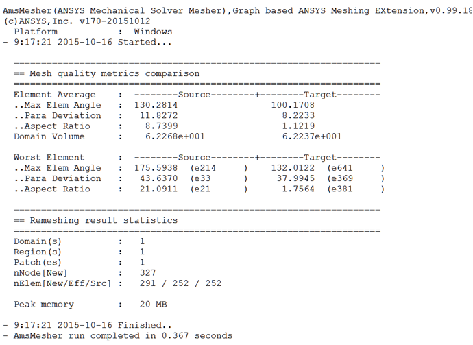
The program writes the average and worst element mesh-quality metrics to the log file, where remeshing statistical data are available to help you make additional adjustments to the remeshing control parameters.
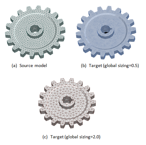
The following figure illustrates the global sizing factor:
A factor of VAL2 > 1
coarsens the model source mesh, and VAL2 < 1
refines the source mesh for the same selected seed elements. .
The factor is the ratio of the average target mesh length over the average
source mesh length. VAL2 < 0.5 refines the
mesh and results in 8x the number of elements in the target mesh as compared
to the source mesh for 3D. The final element number is also affected by
remeshing constraints such as the specified boundary or edge angles, number
of element or material components, contact elements, boundary conditions or
loads, and other factors.
Because the specified global sizing factor that you specify applies to all
remeshings of a nonlinear analysis within a load step, a small value
(VAL2 < 0.7) may eventually lead to an
unnecessarily refined mesh towards the end of the solution (depending on the
initial 2D/3D model, the number of triggered remeshings, and the physics of
the nonlinear deformation during solution). To avoid unreasonable solution
times, therefore, choose a global sizing value carefully.
Typically, Ansys recommends against
coarsening the mesh with the criteria options for mesh refinement; however,
if you wish to do so, specify 1 ≤ VAL2
≤ 1.3. (VAL2 > 1.3 can corrupt the
target model due to excessive coarsening and may cause errors during or
after remeshing.)
For coarsening of unnecessarily refined regions or
regions having no critical features, specify VAL3
> 1. Coarsening remeshing works together with refinement and distortion
remeshing; however it is always considered last. Higher values for
VAL3 are possible but must be chosen carefully to
avoid distorted targeted meshes (for example, when the settings of the
remeshing criteria allow selections of single seed elements).
Debonding Analysis
For a debonding analysis, a highly refined mesh under
completely debonded contact is no longer necessary. To coarsen the mesh in
this region, set VAL3 > 1 via
NLMESH and issue
NLADAPTIVE,,ADD,CONTACT,CZM.
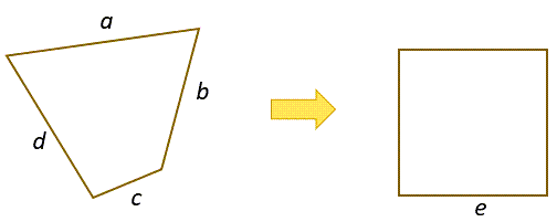
The user input value
VAL3 for coarsening defines an equivalent element
size expansion ratio:
| where: |
a, b,
c, d = element
edge sizes |
e = equivalent
element edge size (calculated from the element area/volume) |
enew
= new equivalent element edge size for remeshing |
e = |
enew
= e x
VAL3 |
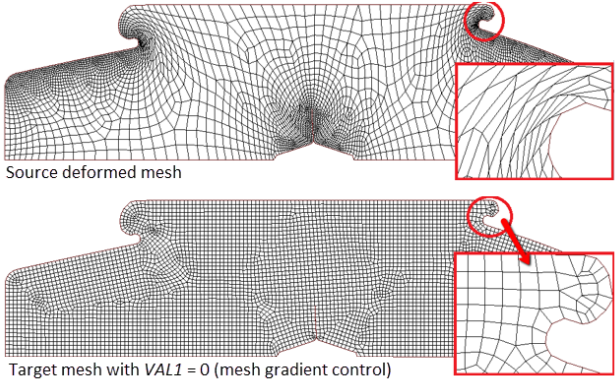
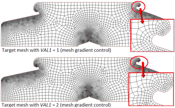
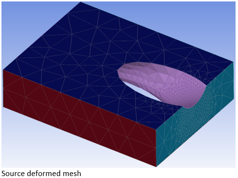
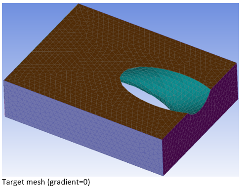
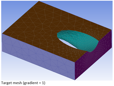
Options are available for 2D and 3D remeshing to retain the size gradient from the source mesh (NLMESH,GRAD):
VAL1 = 0 does not maintain the mesh-size
gradient but generates a uniform mesh in the remeshing regions. |
VAL1 = 1 generates a new mesh and
retains the same local size as the source mesh. |
VAL1 = 2 generates a new mesh and
retains the same local size as the source mesh, but with additional
sizing compensation based on the element-size change during solution due
to large-deformation effects. |
VAL1 = 3 (for 3D analysis only) is
similar to VAL1 = 2 but assumes that perfect
mesh quality is not needed. |
|
Considerations for specifying 2D / 3D size gradient control:
|
2D Mesh-Size Gradient-Control Options:
3D Mesh-Size Gradient-Control Options:

Each remeshing operation generates a corresponding remeshing log in the solver output. The log contains the input and output statistics for that remeshing. The statistical data can help you to make any additional adjustments (if needed) to the remeshing controls (NLMESH).
The Source and
Target columns contain the
corresponding data before and after remeshing. For example, in the 3D
remesh log, the worst element quality is shown based on element volume
skewness, element aspect ratio, and element Jacobian ratios; the worst
element IDs for the corresponding mesh quality metric appear in parentheses
(for example, e7380 indicates that the
element ID is 7380).
Skewness(Vol) is the element volume
skewness, ranging between 0 (perfect element) and 1 (highly distorted
element).
The Aspect Ratio ranges from 1 (perfect
element) to infinity (highly distorted element).
JRatio is the Jacobian ratio, ranging
from 0 (worst element) to 1 (perfect element), and -1 indicates an invalid
element Jacobian ratio.
The Remeshing result statistics section
summarizes the remeshing domain/ or region decomposition data, as follows:
nNode[New] – New nodes
generated in all remeshed regions. |
nElem[New] – New elements
generated in all remeshed regions. |
nELm[Ef] – Effective source
elements that are now remeshed (that is, deleted and
replaced). |
nElm[Sd] – Number of seed
elements from the source mesh. |
nElem[Sr] – Number of
elements available to remesh from the source mesh. |
A partial remesh in selected region(s) is indicated by
nElem[Eff] <
nElem[Src]. A whole selected region(s)
remesh is indicated by nElem[Eff] =
nElem[Src].
The remesh log also shows the peak memory used and the elapsed time for the remeshing process.
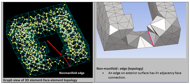
Remeshing typically fails when either of the following conditions exist:
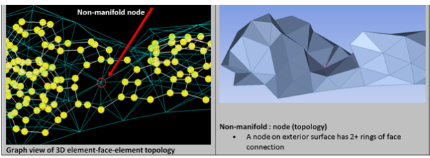
Arbitrary element selection in the remeshing region and partial remeshing with a decomposed element group may create non-manifold FEA geometry, especially for 3D cases where in each atomic region a non-manifold edge or node may exist.
The following figure shows a 3D non-manifold node with two connected exterior faces:
Dealing with Non-manifold Mesh Geometry
The remesher handles 3D non-manifold geometry cases and simple cases of 2D non-manifold geometry automatically.
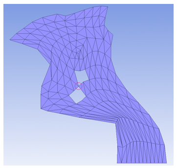
Try the following approaches if 2D non-manifold remeshing issues persist:
Modify any of the remeshing control options (NLMESH). This approach modifies remeshing regions and may help to remove the non-manifold geometry or reduce the complexity in source meshes.
Remesh the entire nonlinear adaptivity model, body, or part (rather than just a portion of the model, body, or part)
Redefine material or element components (insofar as possible)
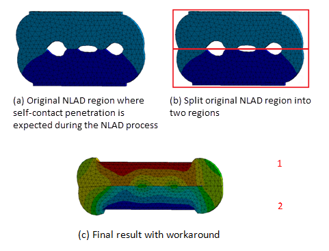
Self-contact penetration means that volume intersections exist in an atomic remeshing region. In a quadratic element (SOLID187or SOLID227), the program considers self-intersection to be the volume intersection of the (shape-function-driven) quadratic surfaces.
In almost all cases, the remesher can handle self-contact automatically leading to a successful remesh.
3D remeshing failure may occur in some rare cases of self-contact. The following figure shows a workaround:
Remeshing failure at a given substep may occur in some nonlinear adaptivity problems, most often because the mesh metrics of the worst element in the target mesh are worse than those of the worst element in the source mesh.
In nonlinear FEA, even a single target element of poor quality in a critical region can cause the solution to diverge. To ensure that convergence is not adversely affected in such cases, the program continues solving using the old mesh and rejects the target mesh, as indicated in the output file at the remeshing substep:

Although Mechanical APDL automates the solution process in the event of remeshing failure, it is not an ideal situation. If many remeshing attempts in a nonlinear solution process are rejected, the solution may diverge, especially when additional loads make the mesh quality worse as the solution progresses. In such cases, a restart may be required with more relaxed shape and/or skewness options (NLADAPTIVE,,,,SHAPE or SKEWNESS, respectively). To a lesser extent, using the remeshing controls (NLMESH) to increase the number of sculpting layers, for example, may also help to achieve successful remeshings after restart.
FEA automatic local remeshing is a complex operation. There may be several reasons why a remeshing failure may be triggered. Two categories of remeshing failure exist:
Direct remeshing failures include cases where the remesher fails to generate a new target mesh based on the source mesh, indicated by errors in the remeshing log in the solver output. The errors can be caused by:
Unacceptable source mesh due to initial model setup
This situation occurs rarely, but is possible when any of the following conditions exist:
Inconsistent element node orientations
Invalid element-node ID references
Invalid component-element ID references
Complicated non-manifold FEA geometry
Due to the generic nature of the FEA local remeshing approach, non-manifold FEA geometry in remeshing regions may occur often. The remesher can handle non-manifold FEA geometry, but may have difficulty in exceptional cases where the source mesh has overly complicated non-manifold geometry, especially in 3D models.
You may deem a given remeshing to be a failure because target mesh quality does not meet your expectations. In this case, consider the following:
The quality of the source mesh at the remeshing substep may already be of sufficient quality.
In this case, perhaps no remeshing is required after all.
Your remeshing requirements (specified via the mesh criterion options) may be too strict.
For most 2D models, try defining a maximum corner angle threshold of 155 to 175. For most 3D models, try defining a skewness threshold of 0.87 to 0.97. These recommendations assume that you check the mesh quality at every substep during the solution.
The program may not be capable of generating a better quality mesh.
Various factors may constrain the program's ability to generate a better quality mesh: many material or element components in the source mesh, tiny remeshing regions, boundary conditions or loads in the remeshing regions, or contact elements in the remeshing regions. One or more of these constraints may adversely affect the quality of the new mesh, even though they may be required by the physics in the model. In this case, try increasing the number of sculpting layers for remeshing (NLMESH).
More mesh-control refinement may be necessary.
In some cases, the target mesh quality may not improve even when using recommended thresholds for the mesh criterion options. In such cases, try modifying other remeshing control parameters (NLMESH) to obtain a better mesh. For example, if a coarse mesh suddenly starts to fill a narrow gap with high element distortion, try to control the element sizing and achieve local remeshing control by specifying fewer sculpting layers for remeshing, eventually improving mesh quality.
If a worse-quality mesh is generated and it is necessary to accept it (not recommended), set a new mesh-acceptance tolerance (NLMESH,QTOL).
Mesh-quality-based remeshing (NLADAPTIVE,,,MESH) and refinement-based remeshing (NLADAPTIVE,,,CONTACT / ENERGY / BOX) can occur simultaneously at the same or in different regions in a finite element model.
Example 2.5: Simultaneous Quality- and Refinement-Based Remeshing
Consider two regions A and B which can be overlapping or non-overlapping:

Assume that region A is controlled by a mesh-quality-based criterion (checking for distortion), and that region B is controlled by a refinement-based criterion.
If regions A and B do not overlap, both regions are remeshed according to their own mesh-control parameter specification. The mesh-quality check and acceptance for the newly generated mesh are also be performed independently based on their respective criteria.
If regions A and region B overlap, the remeshing in the nonoverlapping regions A' = A - C are controlled by the mesh-quality-based criterion, while the remeshing in region B' = B - C are controlled by the refinement-based criterion. Remeshing in overlapping region C is controlled by combining the two mesh-setting parameters. (A mesh-sizing gradient control value of 0 specified in this scenario is converted to 1 automatically.) Finally, the mesh-quality check and acceptance for the newly generated mesh is based on refinement-based criteria.
Coarsening remeshing can be active at the same substep as mesh-quality-based or refinement-based criteria but is always considered last. Elements can only be selected for coarsening when not selected by any other criteria. Neighbored selection of elements for refinement and coarsening is possible but may lead to low-quality meshes and should be avoided via remeshing criteria settings.


