


Several nonlinear adaptivity criteria can be defined to control the mesh during nonlinear solutions:
Also see Specifying Criteria-Checking Frequency.
This criterion is defined for current-technology structural 2D and 3D solid elements. It is based on the magnitude of strain energy of the element compared to the mean strain energy of components to which the element belongs.
During the substep at which nonlinear mesh adaptivity
criteria are checked, if the element’s strain energy is ≥ the mean
strain energy of its components times the user-defined
VAL1 (NLADAPTIVE,,ADD), the element is
either refined via general remeshing or it is split
(NLMESH,REFA,SPLIT), depending on the element types. If the
element strain energy is smaller than the mean strain energy of its components times
the user-defined VAL2
(NLADAPTIVE,,ADD), the element is coarsened via general
remeshing. When splitting remeshing is active, elements are not selected for
coarsening.
Refinement is the default behavior. Coarsening is active only
via a positive VAL2 input value. A negative
VAL1 and a positive VAL2
ignore the refinement option and activates only the coarsening option of the
energy-based criterion. Specify VAL1 >
VAL2 to combine both options; otherwise, the command is
ignored.
The first option of this criterion is used to refine the
mesh to achieve high-accuracy simulation in regions where a high concentration of
stress exists and elements are too large. The second option of this criterion is
used to coarsen the element size and reduce the numerical effort in regions where
the strain energy is low, indicating regions with no critical features. It can also
be used to refine or coarsen the mesh at certain intervals of substeps if a very
small value or 0 is input for VAL1 or a high value is
input for VAL2, respectively.
This criterion is defined for current-technology structural 2D and 3D solid elements. A region is defined in the global Cartesian coordinates.
By default, if all nodes of an element are within the
defined region during the substep at which nonlinear mesh adaptivity criteria are
checked, the element is either refined via general remeshing or it is split
(NLMESH,REFA,SPLIT), depending on the element types. If
VAL7 = COAR (NLADAPTIVE,,ADD), the
element is coarsened via general remeshing instead. Because splitting remeshing is
not supported with coarsening, elements are not selected.
The criterion is used to refine the mesh in regions where it is difficult to predict which elements of the model will be present, or move in to. For example, it is commonly used in rubber seal analysis where small cavities are filled by the deformation of a compressed seal.
In contrast, when VAL7 = COAR, the
criterion is used to coarsen the mesh in regions where the fine meshes are not
required. For example, in an extrusion process, the extruded portion may not require
a fine mesh.
If some elements could potentially move into two different regions, define two different components for the same elements so that one component can be associated with each region.
The following types of contact-based criteria are available for nonlinear adaptivity:
This criterion is defined for target elements only (as the component that bears the criterion consists of target elements), but defines how solid elements underneath corresponding contact elements should be split or refined via general remeshing. This criterion is defined by the number of contact elements which should be in contact with each target element of a component. During the substep at which mesh nonlinear criteria are checked, if the number of contact elements in contact with the target element is less than the defined value, the solid element underneath the contact element is split or refined via general remeshing. Because the solid elements are split or refined, contact elements on the faces of the solid elements are regenerated as well.
This criterion allows a contact region to follow the geometry of targets more accurately. If a target has a large number of small fillets or round angles, or if it forms small cavities, splitting or mesh refinement could make convergence more difficult. The desired number of elements may not be reached when the solution is complete if the checking frequency is set too low. If the deformation history of the contact elements indicates that they have moved away from the target elements, refinement pauses (even if the desired number of contact elements has not been obtained); refinement resumes when the program determines that the contact elements have moved toward the target elements. Exercise caution when applying on flexible-flexible contact pairs; other nonlinear adaptivity refinement criteria (position-based (NLADAPTIVE,,,BOX) or energy-based (NLADAPTIVE,,,ENERGY)) definitions on the same underlying bodies may generate unexpected remeshing patterns.
If a given target element has multiple contact-based criteria defined through different components, the program uses the strictest criterion. For example, if the desired number of elements is defined as 5 in component A and 7 in component B, the program uses 7 as the criterion for a target element present in both components.
This criterion is defined for contact elements having surface wear, specified
via TB,WEAR. With this option, you define the critical ratio
of magnitude of wear at the contact element to the average depth of the solid
element underlying the contact element (input as VAL1
on NLADAPTIVE). When the amount of wear at a contact element
exceeds this critical value, the nonlinear adaptivity criterion is met and the
mesh is morphed to improve the
quality of the mesh.
During the mesh morphing process, the accumulated wear is first applied and the nodal coordinates are updated to reflect the material loss due to wear. Next, the mesh is morphed to improve the quality. At the start of the subsequent analysis, the wear is initialized to zero and starts accumulating anew.
If a given contact element has multiple contact wear-based criteria defined through different components, the program uses the strictest criterion. For example, if the critical ratio of wear to underlying solid element depth is defined as 0.25 in component A and 0.5 in components B, the program uses 0.25 as the criterion for a contact element present in both components.
The wear criterion for nonlinear mesh adaptivity cannot be combined with any other nonlinear mesh adaptivity criterion.
For more information about using the wear-based criterion, see Improving Mesh Quality During Wear in the Contact Technology Guide.
This criterion (NLADAPTIVE,,ADD,CONTACT,CZM) is defined for target elements only (as the component bearing the criterion consists of target elements) but determines how solid elements underneath corresponding contact and deformable target elements should be refined/coarsened via general remeshing. (Element splitting is possible but not recommended, as splitting generates an excessively large number of elements because it occurs repeatedly.)
The corresponding contact elements must have a cohesive zone material (TB,CZM).
Refinement Remeshing:
Set
VAL1on NLADAPTIVE to define the maximal relative change in energy released due to debonding between the current substep and a nonlinear adaptivity reference substep in the contact element. The reference substep is defined internally and is the first solved substep or the substep after the last successful remeshing.When the relative energy change exceeds the critical value, the nonlinear adaptivity criterion is met and the solid elements under the corresponding contact and target element are selected for remeshing.
Set
VAL2on NLADAPTIVE to define the maximal difference in the damage parameter between neighboring contact elements (evaluated at the integration points) in the current substep.VAL2does not support exponential cohesive-zone material models (TB,CZM,,,,EXPO).When the damage value changes from zero to non-zero (damage initiation), or when the difference between the maximal and the minimal damage parameter is larger than
VAL2, the nonlinear adaptivity criterion is met and the solid elements under the corresponding contact and target element are selected for remeshing.
Coarsening Remeshing:
Set
VAL3> 1 on NLMESH,SRAT to select solid elements under the completely debonded (damaged and/or contact status open) contact and target elements. The criterion (NLADAPTIVE,,ADD,CONTACT,CZM) must be active.Coarsening is not supported for exponential CZM (TB,CZM,,,,EXPO).
To activate the criterion, set at least one least one
input value (VAL1 and/or
VAL2). You can apply them separately or together.
If you apply both, the selection for remeshing occurs if
either nonlinear adaptivity criterion is met.
When multiple solid nonlinear adaptivity components exist, the underlying bodies of the solids of the contact surface (contact and target side) with a target component must also be part of a nonlinear adaptivity component for proper remeshing.
For soft material in the base material, use additional mesh-quality-based criteria on the solids to minimize element distortion.
Example 2.1: 2D Setting the Nonlinear Adaptivity Cohesive-Zone Criterion
This criterion setting is based on the relative change in released energy
defined on a target nonlinear adaptivity component with the mesh-quality
criterion on two solid components. The components consist of the respective
solid elements under the target and contact elements of the cohesive-zone
interface. Increasing VAL1 of the criterion leads
to more localized remeshing, while decreasing it leads to refinement over
larger areas.
Setting VAL3 > 1 on
NLMESH,SRAT activates the check for coarsening in the
defined component for the same defined substeps. If
VAL3 is not specified, only refinement remeshing
is active.
nlad,comptarg,on,,,5             ! check target component every 5th substep
nlad,comptarg,add,contact,czm,1  ! remesh if difference in relative released energy is > 1
nlad,comp1,on,,,2                ! check 1st solid component every 2nd substep
nlad,comp1,add,mesh,shape,160    ! remesh if element shapeangle > 160
nlad,comp2,on,,,2                ! check 2nd solid component every 2nd substep
nlad,comp2,add,meshshape,160     ! remesh if element corner angle >160
The reference substep is the reference mesh configuration from which the relative increment of released energy is calculated for evaluating the CZM criterion.
Consider a typical nonlinear adaptivity problem with multiple remeshings:
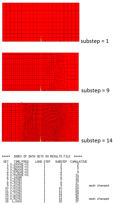
At the start of the analysis, the reference substep is the starting substep. As the solution progresses with remeshing, the reference substep shifts to the last remeshing substep:
| Checking Criteria Between Substeps | Corresponding Reference Substep |
|---|---|
| 1 – 8 | 1 |
| 9 - 13 | 9 |
| 14 - 15 | 14 |
The element components chosen to define a mesh-quality-based criterion should include only the elements falling into the large-deformation region; otherwise, the criterion may cause a larger region than necessary to be remeshed. Because the boundaries of the components cannot be remeshed, it is good practice to make the boundaries as smooth as possible, like the boundaries of the model, materials, element types, etc.
The mesh-quality-based criterion (NLADAPTIVE,,,MESH) has two options:
This criterion applies to 2D plane elements PLANE182
and PLANE222. Mesh quality is defined by element shape
(NLADAPTIVE,,,MESH,SHAPE,VAL1).
It works for all stress states options: plane stress, plane strain,
axisymmetric, and generalized plane strain (for
PLANE182 only). The mesh quality value is defined
by the element's maximum corner angle: when the angle equals or exceeds the
specified threshold (set via NLADAPTIVE), the element is
identified as a seed element to be remeshed.
The recommended maximum corner angle is 150 to 175, although any positive value between 90 and 180 is valid. A larger value results in fewer remeshings but enables remeshing from a more distorted original mesh. A maximum corner angle that is too large can introduce mapping errors, leading to residual forces that cannot be balanced in later substeps. A value that is too small causes unnecessary meshing, or a new mesh that is not much better than the original mesh.
This criterion applies to structural 3D solid elements SOLID187 (a quadratic tetrahedral element) and SOLID285 (a linear tetrahedral element).
For SOLID187, mesh quality is defined by element
skewness and the maximum Jacobian ratio at Gaussian points
(NLADAPTIVE,,,MESH,SKEWNESS,VAL1,VAL2).
For SOLID285, mesh quality is defined by element
skewness only
(NLADAPTIVE,,,MESH,SKEWNESS,VAL1).
Skewness (VAL1) is calculated based on the
linearized element shape for SOLID187 and SOLID227,
and the true element shape for SOLID285, formed by
connecting the corner nodes only and defined as:

where  is the volume of the element under calculation and
 is the volume of the standard tetrahedral linear element
inscribed in the same sphere as the element under calculation.
is the volume of the standard tetrahedral linear element
inscribed in the same sphere as the element under calculation.
When the element under calculation has an ideal shape (that of a standard
tetrahedral element),  and skewness = 0. When the element under calculation has
the least ideal shape (that of a flat element),
and skewness = 0. When the element under calculation has
the least ideal shape (that of a flat element),  and skewness =1. For the linear tetrahedral element,
therefore, skewness is always between 0 and 1, with 1 being a flat
element.
and skewness =1. For the linear tetrahedral element,
therefore, skewness is always between 0 and 1, with 1 being a flat
element.
The skewness value serves as the threshold value for detecting an element to remesh. When an element’s skewness is >= the specified threshold, that element is identified as a seed element to be remeshed.
The recommended skewness value is approximately 0.9 to 0.95. An excessively small skewness value may lead to many unnecessary remeshings, and an excessively large value may cause remeshing to occur too late for the subsequent substep to converge.
While skewness (VAL1) is sufficient for
representing the shape of a linear tetrahedral element (such as
SOLID285), a quadratic tetrahedral element
(SOLID187 or SOLID227)
requires another parameter to represent its true higher-order nature. The
maximum Jacobian ratio at Gaussian point (VAL2)
is used in nonlinear adaptivity
(NLADAPTIVE,,,MESH,SKEWNESS,VAL1,VAL2),
defined as:

where  and
and  are the minimum and maximum determinants (respectively) of
the Jacobian matrix at Gaussian points.
are the minimum and maximum determinants (respectively) of
the Jacobian matrix at Gaussian points.
When the element under calculation has an ideal shape (that of a standard
tetrahedral element),  =
=  and
and  = 1.
= 1.
When the element under calculation has a distorted shape,  is between 0 and 1.
When the element is turned inside-out and can no longer map on a
one-to-one basis,  = -1 is reported.
The Jacobian ratio also serves as the threshold value for detecting an element to remesh. When an element's Jacobian ratio is <= the specified threshold, that element is identified as a seed element to be remeshed.
The recommended Jacobian ratio is approximately 0.01 to 0.15. An excessively large ratio value may lead to many unnecessary remeshings, and an excessively small ratio value may cause remeshing to occur too late for the subsequent substep to converge.
If one condition is met when both skewness and Jacobian ratio are defined for SOLID187 or SOLID227, the element is identified as a seed element to be remeshed.
The element-removal-based criterion (NLADAPTIVE,,,REMELM) is used to remove elements from a deformed body during the nonlinear solution process. This criterion is applicable to all PLANE182 2D problems (plane stress, plane strain, generalized plane strain, and axisymmetric), for all materials with small and large deformation behaviors (NLGEOM,OFF and NLGEOM,ON) as supported in conventional NLAD. As with other NLADAPTIVE criteria, the element removal criterion is also driven by element components. This means that only the elements included in that component description are potential candidates for removal. The locations of the removable elements are determined by the supported options of this criterion. Any number of elements may be removed at a given substep. As with other NLADAPTIVE criteria, elements may be removed at any stage of a load step.
Adaptive element removal is useful in the following scenarios:
In analyses where strain measure levels become elevated beyond the actual failure strain of the material, the affected integration points are no longer capable of carrying loads. Therefore, automatically removing the higher strain elements at that load level and continuing the analysis is a more realistic way to represent the model behavior.
In some analyses, there may be regions in the model that are never critically stressed and therefore do not contribute to the true performance of the model. In such cases, you can use automatic element removal to introduce gaps in the regions of very low strains.
Sometimes, there is a need to selectively remove a few elements during the solution due to some problematic behaviors or expected simulation requirements. This can be achieved with the element removal criterion at the time or substep of choice.
The element-removal-based criterion has three options:
For both ESTN and PSTN options, elements for removal are part of a NLAD component
and are selected automatically, potentially throughout the solution process spanning
multiple substeps, and removed in multiple substeps depending on the option and its
VAL1 and VAL2. It is
possible to set the same set of elements with two different component names and have
two options defined. In that case, the gap is opened based on the most conservative
values of the error indicators.
In general, as an implicit scheme, the adaptive scheme manages the sudden material removal (when the elements are removed) by proper residual rebalancing. Depending on the stress state and the total volume of material removed in a single substep, there may be convergence difficulties. Usually, you can apply a distortion-based remeshing criterion with element removal to correct the large distortions that may happen in the new element gaps with residual rebalancing.
As the elements are removed from a deformed body, the resulting gaps may change shape or completely close due to residual equilibration and load application. In order to avoid the interpenetration of the gap surfaces during closure, you can use the NLMESH,DCON command to automatically generate contact and target elements in the gaps. When element gaps are introduced on boundaries with contact and target elements, the NLMESH,DCON command also generates new contact and target elements in the new gaps that belong to the same pair as the existing contact and target elements in addition to a possible new self-contact pair in the new gaps.
This section covers the following topics:
This option uses the maximum equivalent strain of all integration points in an element of the relevant component to determine if the element is a candidate for removal. An error indicator (E) is computed for each integration point based on its equivalent strain measure (S) as following:
If both
VAL1andVAL2are defined:E = ||(S – 0.5(
VAL1+VAL2))|| ifVAL1<= S <=VAL2.E = 0 otherwise.
If only
VAL1is defined:E = ||(S –
VAL1)|| if S >=VAL1.E = 0 otherwise.
If only
VAL2is defined:E = ||(S –
VAL2)|| if S <=VAL2.E = 0 otherwise.
Any non-zero error indicator in any integration point of an element makes the element a candidate for removal.
This option uses the maximum principal strain of all integration points in an element of the relevant component to determine if the element is a candidate for removal. An error indicator (E) is computed for each integration point based on its principal strain measure (P) as following:
If both
VAL1andVAL2are defined:E = ||(P – 0.5(
VAL1+VAL2))|| ifVAL1<= P <=VAL2.E = 0 otherwise.
If only
VAL1is defined:E = ||(P –
VAL1)|| if P >=VAL1.E = 0 otherwise.
If only
VAL2is defined:E = ||(S –
VAL2)|| if P <=VAL2.E = 0 otherwise.
Any non-zero error indicator in any integration point of an element makes the element a candidate for removal.
This option requires an element component containing the desired elements (based on the initial mesh element IDs) as input for removal. If the desired elements get remeshed or renumbered during solution before the intended manual removal, this option will not work. The element removal is done at a single substep depending on the options in the NLAD command. You can select the elements for removal at the beginning of the solution or the beginning of a load step for a standard element component.
Table 2.1: Element Removal Mechanisms of NLADAPTIVE,,,REMELM Options below describes the similarities and differences in element removal mechanisms between the ESTN/PSTN options and the MANUAL option. Depending on which options are used, there are certain restrictions on how additional NLAD remeshing commands can be used simultaneously in the solution.
Table 2.1: Element Removal Mechanisms of NLADAPTIVE,,,REMELM Options
| ESTN/PSTN | MANUAL |
|---|---|
|
|
The ESTN and PSTN-option-based element removal processes work more like the conventional remeshing approach. Specific elements within the selected components are checked for the options, and the removal candidate elements determined in these options are removed in the substeps based on the frequency and time limits you specify in the corresponding NLADAPTIVE,ON command. Element removals may spread over the solution process as more load is applied and gradually more elements become candidates for removal based on the specific option in question (ESTN or PSTN). Example 2.2: ESTN/PSTN Element Removal Examples lists some examples of how these options can be used for the element removal process.
Example 2.2: ESTN/PSTN Element Removal Examples
CM1 is the component where the element(s) removal is performed.
| Commands | Actions Performed | |
| Example 1 |
NLADAPTIVE,CM1,ADD,REMELM,PSTN,V1,V2 NLADAPTIVE,CM1,,,ON,1 |
Check for elements to be removed from CM1 at every substep. Remove only if element level error indicators for principal strains are within the (V1,V2) interval. |
| Example 2 |
NLADAPTIVE,CM1,ADD,REMELM,PSTN,,V2 NLADAPTIVE,CM1,,,ON,3 |
Check for elements to be removed from CM1 at every third substep. Remove only if element level error indicators for principal strains are smaller than V2. |
| Example 3 |
NLADAPTIVE,CM1,ADD,REMELM,ESTN,V1 NLADAPTIVE,CM1,,,ON,-3,T1,T2 |
Check for elements to be removed from CM1 at three equal timepoints within (T1,T2). Remove only if element level error indicators for equivalent strains are greater than V1. |
As mentioned earlier, conventional remeshing methods can be combined with the ESTN/PSTN-option-driven element removal process. Table 2.2: ESTN/PSTN Element Removal and Remeshing Combinations shows the scenarios under which these combinations may be activated and their limitations.
Table 2.2: ESTN/PSTN Element Removal and Remeshing Combinations
| Case Description | Process and Result | ||
|---|---|---|---|
| Case A | |||
|
Component COMP is defined for both element removal and remeshing. Example commands:
|
Two process scenarios:
| ||
| Case B | |||
|
Different components are defined for element removal and remeshing. These components do not intersect. |
Two process scenarios. Both work without issues:
| ||
| Case C | |||
| Different components are defined for element removal and remeshing. These components intersect. | Same as Case A. | ||
Element removal and remeshing can occur in the same substep, but remeshing always takes precedence. This means that after remeshing, if none of the elements marked for removal at the current substep has been removed or renumbered, element removal will be skipped for the substep. Therefore, if element removal and remeshing are activated on the same component and/or on the same body, you should ensure that the element removal substep does not coincide with the remeshing substep. This restriction, however, is not applicable if element removal and remeshing occur on different bodies in the model.
Unlike the ESTN/PSTN options, with the MANUAL option, all candidate elements in the component are removed in one substep. Example 2.3: Manual Element Removal Examples lists some example processes of manual element removal in the nonlinear adaptivity environment.
Example 2.3: Manual Element Removal Examples
 =
User-selected elements for removal from component 'C1'.
=
User-selected elements for removal from component 'C1'.

| Commands | Actions Performed | |
| Example 1 |
NLADAPTIVE,C1,ADD,REMELM,MANUAL NLADAPTIVE,C1,ON,1 |
Remove all elements from C1 at the first substep of the load step. |
| Example 2 |
NLADAPTIVE,C1,ADD,REMELM,MANUAL NLADAPTIVE,C1,ON,3 |
Remove all elements from C1 at the third substep of the load step. |
| Example 3 |
NLADAPTIVE,C1,ADD,REMELM,MANUAL NLADAPTIVE,C1,ON,-1,T1,T3 |
Remove all elements from C1 at the substep (T3-T1)/2. |
Note: If there are other remeshing based NLAD commands (like refinement) issued with NLADAPTIVE,,REMELM, then certain remeshing restrictions may cause remeshing failures.
Although remeshing-based NLAD commands are allowed with the manual element removal, there are certain restrictions on how it can be applied to a given problem. The details are shown in Table 2.3: Manual Element Removal and Remeshing Combinations. Note that component C1 will be entirely removed if it is defined with the MANUAL option.
Table 2.3: Manual Element Removal and Remeshing Combinations
| Case Description | Process and Result | ||
|---|---|---|---|
| Case A | |||
|
Two components are defined:
Example commands:
|
Two process scenarios:
| ||
| Case B | |||
|
Only component C1 (elements to be removed) is defined. Example commands:
|
Two process scenarios:
| ||
In the element removal process in a deformed body, it is fairly common for initially created element gaps to distort to more general shapes, expand, contract, or close completely during deformation due to residual equilibration and load application. The NLMESH,DCON command identifies the gaps created in that process and creates unique self-contact pairs to prevent interpenetration if the gaps close due to subsequent large deformation.
Elements may be removed from the body interior or the boundary, and element gaps may be introduced on boundaries with contact and target elements, boundaries with surface effect elements, boundaries with imposed loads and boundary conditions, and free boundaries. If there are element gaps on an existing model boundary where contact and target elements are already present, the NLMESH,DCON command also generates a set of new contact and target elements in the new gaps with the same Real IDs as the existing contact and target elements in the region of the removed elements. Figure 2.27: Generation of New Contact and Target Elements in New Element Gaps and Subsequent Closure below describes that process.
You must be careful when introducing element gaps on surfaces with loads and/or boundary conditions as these loads and/or boundary conditions are not reapplied on the new surfaces generated by the element removal.
Figure 2.27: Generation of New Contact and Target Elements in New Element Gaps and Subsequent Closure

In the figure above, the element marked with a white circle in (A) is removed from a deformed body. (B1) shows the subsequent deformation due to residual minimization and the addition of extra loads. (B2) shows the new contact and target elements that are automatically generated. These new elements include a new self-contact pair which enables correct closure of the gap and additional new contact elements which belong to the existing contact pairs in the removed region. Finally, in (C), at the end of loading and remeshings, the closure of the element gap is shown with proper contact pressures. Note that the remeshing close to the element gap follows the same principle of conventional NLAD remeshing, which allows the generation of new contact elements and mapping with equilibration.